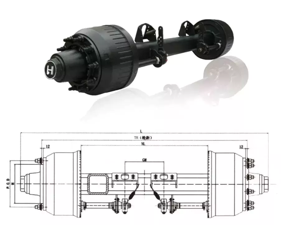
304 entrance axle 35-40 hp tractor areas wheel reduction housing
OEM/ODM
OEM/ODM Service Supplied
Rongnan collection wheeled tractor generate axle is specially produced for the growth pattern of 4wd tractor, It can be assembled on a broad range of horsepower tractor. Elements are common & suitable for a variety of types of domestic wheeled tractors. It has the positive aspects of aesthetics, security and trustworthiness. With compact composition, Push axle is performance on higher transmission, basic upkeep, convenient matching, and excellent functionality, which is adapt to paddy field, dry discipline and other intricate running atmosphere. It gives trustworthy assure for the tractor area procedure.
An axle is the central shaft of a rotating gear or wheel. Axles are either fixed to the wheels or mounted directly to the vehicle. They rotate with the wheels and can be equipped with bearings for smooth operation. Axle types include Czpt axles, Drop out axles, and Splines. Each has a unique design and function.
Spindles
The spindles on a vehicle’s axle are the main components that connect the wheels to the axle. They mount the wheels on the axle and fasten the braking system to the axle assembly. The spindles are fastened to the axle assembly with king pins and ball joints. They also fasten the wheel hub to the spindle via a castelated nut. In both applications, axle spindles are pivot points that are used to make turning motion possible. There are three types of spindles for an axle. Typically, the spindles are bolted to the ends of a tubular axle, which is suspended by springs. The third type is a short stub axle, which uses a torsion beam to help the axle maintain a smooth ride over bumpy terrain.
Czpt axles
Czpt axles are available in a variety of configurations. From beam-to-independent designs to single-point-to-double-point designs, there’s a Czpt axle to fit your needs. These axles are designed to provide maximum power in a small package. Czpt has a proven track record of innovation and durability. Czpt axles are found in front-end steering vehicles and heavy-duty pickups. Some models only use the front axle. There are also Czpt axles for light-duty pickups. You can easily recognize a Czpt axle by its shape. Some online sources offer diagrams to help you identify the axle. Among the most popular Czpt axles are the Czpt 60 and the Czpt 44. Both models are desirable in their own right. You can order Czpt axle parts from the Czpt website. These products include u joints, differential cases, and loc pins. These parts can be purchased online, and they will be delivered right to your door. In addition to the Czpt 60 front axle, Czpt axles also feature great aftermarket support. They can be upgraded with locking differentials, limited slip differentials, and high-capacity differential covers. They also feature heat-sinks that keep the axle cool. Czpt axles are also compatible with nearly every traction aid in the market. Czpt is a global leader in driveline products and genuine service parts. With over a century of experience manufacturing quality products, Czpt axles provide performance and reliability.
Drop out axles
Drop out axles are crucial for mounting a front wheel to a bike. If the axles are not present, the wheel will not be able to be mounted. These dropouts are made of either steel or aluminum. They are 5.8mm thick. Axles with quick release axle hubs are compatible with steel dropouts. Axle manufacturers make different dropout axles that are compatible with different axle sizes. These axles are available in a wide range of styles. The Shimano modular dropout, for example, is available in three main axle specifications: Road, Track, and Maxle. These dropouts are also available with different axle pinions. Drop out axles can be quick release or through. Quick release axles are lighter than thru axles. They weigh approximately 60 to 80 grams. The difference between quick release and thru axles is in the thread pitch. Quick release axles have a smaller pitch than thru axles, which allows for easier installation and removal. Thru axles are a popular choice for mountain bikes. They prevent the front wheel from coming out while riding. They are more secure and can prevent a wheel from coming off when moving. They are usually made of a thicker rod and screw into the frame. Both types of dropouts have their advantages and disadvantages. You should choose the type that works best for your needs. This is a decision that you will have to make on your own.
CV joints
When your vehicle is in motion, the CV joints on your axle transfer torque to the wheels. Although these joints come in a wide variety of designs, they all contain a bearing assembly that allows them to move. These joints are protected by a rubber boot that is filled with grease to keep them lubricated. When they become worn, they can cause your car to shudder and vibrate while accelerating. To avoid joint failure, it is important to keep the CV joints free of road debris. Luckily, the boots are made of durable rubber, and a good quality one can last 100,000 miles. Unfortunately, if the rubber boot is torn, dirt and moisture can leak into the joint. Therefore, it’s important to inspect the boots regularly, and replace them if necessary. Damaged CV joints can make control of your vehicle extremely difficult. They can also cause your steering wheel to jerk when you’re accelerating, increasing the risk of an accident. A damaged CV joint can also lead to axle separation, which can cause massive damage and a serious safety risk. However, if you don’t have the funds to replace the joint, you can repair the problem by applying a sleeve. Unlike other drive systems, CV axles can transfer torque at an angle. This is possible because of the constant velocity joints. They’re akin to the univeersal joints on tail shafts, except they work on a much larger angle. This allows the drive shaft to transfer torque to the front wheels smoothly. It also allows the axle to move up and down. A damaged CV axle will make a characteristic clicking sound when you’re turning the vehicle. This noise is very distinctive and can only be heard when the vehicle is in motion. If you hear this noise, then the joint is worn and is in danger of failure. If this noise is loud and consistent, you’ll need to replace it. editor by czh 2022-12-23
CZPT MACHINERY, located in HangZhou city, China, the capital of wood-based panel manufacturing In China. mainly manufacture and supply wood log debarker, veneer peeling machine, veneer slicer machine, veneer drying machine, plywood hot press machine, glue spreader, cold press machine, plywood paving machine, plywood edge cutting machine, sanding machine. Can customize all the plywood machine according to clients requirements
Q1: Are you a factory or retailers? A1: We are a factory with 20 years.
Q2: Where is your factory located? A2: We are located in HangZhou city, ZheJiang province, China.
Q3: How can we go to visit your factory? A3: There are fights/long-trip bus/train from ZheJiang , ZheJiang , HangZhou, HangZhou city, etc to HangZhou city.
Q4: Which seaport you export from? A4: We mainly export machines from HangZhou city, sometimes also from ZheJiang , etc.
Q5: How many years of experience does your company have in the manufacture and exporting? A5: Our company has 30 years of manufacturing experience and 13 years of exporting experience.
Q6: How to solve the after-sales problem? A6: We can provide online guidance, and the company has professional overseas teams to help solve the problem.
Contact Us
Company Information
HangZhou Xihu (West Lake) Dis. Shunda Machinery Manufacture Company Limited.(HangZhou Xihu (West Lake) Dis. Shunda Imp.& Exp., Ltd.) is a professional machinery company in producing and selling plywood machine, particle board machine, MDF/HDF machine, flooring machine, lamination press, located in beautiful logistics city “HangZhou”, and also won a license for direct import and export by the state government.
After 20 years’ experience and development, it always adheres to the independent innovation and scientific development way. Now leading products and auxiliary products follow the market demand and upgrade increasing. Specializing in the production of various professional plywood, flooring, laminated board, particle board, MDF/HDF, OSB complete lines and equipment. Machines are also exported to 20 countries and districts in Asia, Europe, Africa and America with high-quality products and best service, it has won the recognition of customers inner China and abroad.
YIHE machinery, hailed in wood-based machinery, flight being as leading manufacturers and exporters in the same industry, one-time cooperation, whole life friends.
What You Should Know About Axle Shafts
There are several things you should know about axle shafts. These include what materials they’re made of, how they’re constructed, and the signs of wear and tear. Read on to learn more about axle shafts and how to properly maintain them. Axle shafts are a crucial part of any vehicle. But how can you tell if 1 is worn out? Here are some tips that can help you determine whether it’s time to replace it.
Materials used for axle shafts
When it comes to materials used in axle shafts, there are 2 common types of materials. One is carbon fiber, which is relatively uncommon for linear applications. Carbon fiber shafting is produced by CZPT(r). The main benefit of carbon fiber shafting is its ultra-low weight. A carbon fiber shaft of 20mm diameter weighs just 0.17kg, as opposed to 2.46kg for a steel shaft of the same size. The other type of material used in axle shafts is forged steel. This material is strong, but it is difficult to machine. The resulting material has residual stresses, voids, and hard spots that make it unsuitable for some applications. A forged steel shaft will not be able to be refinished to its original dimensions. In such cases, the shaft must be machined down to reduce the material’s hardness. Alternatively, you can choose to purchase a through-hardened shaft. These types of axle shafts are suitable for light cars and those that use single bearings on their hub. However, the increased diameter of the axle shaft will result in less resistance to shock loads and torsional forces. For these applications, it is best to use medium-carbon alloy steel (MCA), which contains nickel and chromium. In addition, you may also need to jack up your vehicle to replace the axle shaft. The spline features of the axle shaft must mate with the spline feature on the axle assembly. The spline feature has a slight curve that optimizes contact surface area and distribution of load. The process involves hobbing and rolling, and it requires special tooling to form this profile. However, it is important to note that an axle shaft with a cut spline will have a 30% smaller diameter than the corresponding 1 with an involute profile. Another common material is the 300M alloy, which is a modified 4340 chromoly. This alloy provides additional strength, but is more prone to cracking. For this reason, this alloy isn’t suited for street-driven vehicles. Axle shafts made from this alloy are magnaflushed to detect cracks before they cause catastrophic failure. This heat treatment is not as effective as the other materials, but it is still a good choice for axle shafts.
Construction
There are 3 basic types of axle shafts: fully floating, three-quarter floating, and semi-floating. Depending on how the shaft is used, the axles can be either stationary or fully floating. Fully floating axle shafts are most common, but there are exceptions. Axle shafts may also be floating or stationary, or they may be fixed. When they are stationary, they are known as non-floating axles. Different alloys have different properties. High-carbon steels are harder than low-carbon steels, while medium-carbon steels are less ductile. Medium-carbon steel is often used in axle shafts. Some shafts contain additional metals, including silicon, nickel, and copper, for case hardening. High-carbon steels are preferred over low-carbon steels. Axle shafts with high carbon content often have better heat-treatability than OE ones. A semi-floating axle shaft has a single bearing between the hub and casing, relieving the main shear stress on the shaft but must still withstand other stresses. A half shaft needs to withstand bending loads from side thrust during cornering while transmitting driving torque. A three-quarter floating axle shaft is typically fitted to commercial vehicles that are more capable of handling higher axle loads and torque. However, it is possible to replace or upgrade the axle shaft with a replacement axle shaft, but this will require jacking the vehicle and removing the studs. A half-floating axle is an alternative to a fixed-length rear axle. This axle design is ideal for mid-size trucks. It supports the weight of the mid-size truck and may support mid-size trucks with high towing capacities. The axle housing supports the inner end of the axle and also takes up the end thrust from the vehicle’s tires. A three-quarter floating axle, on the other hand, is a complex type that is not as simple as a semi-floating axle. Axle shafts are heavy-duty load-bearing components that transmit rotational force from the rear differential gearbox to the rear wheels. The half shaft and the axle casing support the road wheel. Below is a diagram of different forces that can occur in the axle assembly depending on operating conditions. The total weight of the vehicle’s rear can exert a bending action on the half shaft, and the overhanging section of the shaft can be subject to a shearing force.
Symptoms of wear out
The constant velocity axle, also called the half shaft, transmits power from the transmission to the wheels, allowing the vehicle to move forward. When it fails, it can result in many problems. Here are 4 common symptoms of a bad CV axle: Bad vibrations: If you notice any sort of abnormal vibration while driving, this may be a sign of axle damage. Vibrations may accompany a strange noise coming from under the vehicle. You may also notice tire wobble. It is important to repair this problem as it could be harmful to your car’s handling and comfort. A damaged axle is generally accompanied by other problems, including a weak braking response. A creaking or popping sound: If you hear this noise when turning your vehicle, you probably have a worn out CV axle. When the CV joints lose their balance, the driveshaft is no longer supported by the U-joints. This can cause a lot of vibrations, which can reduce your vehicle’s comfort and safety. Fortunately, there are easy ways to check for worn CV axles. CV joints: A CV joint is located at each end of the axle shaft. In front-wheel drive vehicles, there are 2 CV joints, 1 on each axle. The outer CV joint connects the axle shaft to the wheel and experiences more movement. In fact, the CV joints are only as good as the boot. The most common symptoms of a failed CV joint include clicking and popping noises while turning or when accelerating. CV joint: Oftentimes, CV joints wear out half of the axle shaft. While repairing a CV joint is a viable repair, it is more expensive than replacing the axle. In most cases, you should replace the CV joint. Replacement will save you time and money. ACV joints are a vital part of your vehicle’s drivetrain. Even if they are worn, they should be checked if they are loose. Unresponsive acceleration: The vehicle may be jerky, shuddering, or slipping. This could be caused by a bent axle. The problem may be a loose U-joint or center bearing, and you should have your vehicle inspected immediately by a qualified mechanic. If you notice jerkiness, have a mechanic check the CV joints and other components of the vehicle. If these components are not working properly, the vehicle may be dangerous.
Maintenance
There are several points of concern regarding the maintenance of axle shafts. It is imperative to check the axle for any damage and to lubricate it. If it is clean, it may be lubricated and is working properly. If not, it will require replacement. The CV boots need to be replaced. A broken axle shaft can result in catastrophic damage to the transmission or even cause an accident. Fortunately, there are several simple ways to maintain the axle shaft. In addition to oil changes, it is important to check the differential lube level. Some differentials need cleaning or repacking every so often. CZPT Moreno Valley, CA technicians know how to inspect and maintain axles, and they can help you determine if a problem is affecting your vehicle’s performance. Some common signs of axle problems include excessive vibrations, clunking, and a high-pitched howling noise. If you’ve noticed any of these warning signs, contact your vehicle’s manufacturer. Most manufacturers offer service for their axles. If it’s too rusted or damaged, they’ll replace it for you for free. If you’re in doubt, you can take it to a service center for a repair. They’ll be happy to assist you in any aspect of your vehicle’s maintenance. It’s never too early to begin. CZPT Moreno Valley, CA technicians are well-versed in the repair of axles and differentials. The CV joint, which connects the car’s transmission to the rear wheels, is responsible for transferring the power from the engine to the wheels. Aside from the CV joint, there are also protective boots on both ends of the axle shaft. The protective boots can tear with age or use. When they tear, they allow grease and debris to escape and get into the joint. While the CV joint is the most obvious place to replace it, this isn’t a time to ignore this important component. Taking care of the CV joint will protect your car from costly breakdowns at the track. While servicing half shafts can help prevent costly replacement of CV joints, it’s best to do it once a season or halfway through the season. ACV joints are essential for your car’s safety and function.
Letterpress 4 color flexographic printing machine 1.;The main features 1.;Take it easy,; accurate color,; long life 2.;The use of motors,; variable frequency speed control,; saving electricity,; running small fluctuations 3.;Off printing roll automatic stop the ink-running motor,; and up-printing roll automatic start running the ink 4.;The use of special synchronous belt,; print size is accurate,; 5.;There are 2 sets of heating devices,; including central heating and constant temperature control system for packet control 6.;Low-roller special steel processing,; and special process,; and plating thickness of 0.;1mm protective layer of hard chromium 7 Alloy roll with hard oxidation,; treating by dynamic balance,; static balanced 8 With a cold wind bellows,; and can effectively prevent produce with ink adhesion after printing 9.;The Print produce are clear and good arrangement quality 10.;Bearing:;NSK,; Japan brand,; Germany ASNU aluminum alloy roll 2.;Main Technical Parameter:;
Model
CJS884-6
What is a drive shaft?
If you notice a clicking noise while driving, it is most likely the driveshaft. An experienced auto mechanic will be able to tell you if the noise is coming from both sides or from 1 side. If it only happens on 1 side, you should check it. If you notice noise on both sides, you should contact a mechanic. In either case, a replacement driveshaft should be easy to find.
The drive shaft is a mechanical part
A driveshaft is a mechanical device that transmits rotation and torque from the engine to the wheels of the vehicle. This component is essential to the operation of any driveline, as the mechanical power from the engine is transmitted to the PTO (power take-off) shaft, which hydraulically transmits that power to connected equipment. Different drive shafts contain different combinations of joints to compensate for changes in shaft length and angle. Some types of drive shafts include connecting shafts, internal constant velocity joints, and external fixed joints. They also contain anti-lock system rings and torsional dampers to prevent overloading the axle or causing the wheels to lock. Although driveshafts are relatively light, they need to handle a lot of torque. Torque applied to the drive shaft produces torsional and shear stresses. Because they have to withstand torque, these shafts are designed to be lightweight and have little inertia or weight. Therefore, they usually have a joint, coupling or rod between the 2 parts. Components can also be bent to accommodate changes in the distance between them. The drive shaft can be made from a variety of materials. The most common material for these components is steel, although alloy steels are often used for high-strength applications. Alloy steel, chromium or vanadium are other materials that can be used. The type of material used depends on the application and size of the component. In many cases, metal driveshafts are the most durable and cheapest option. Plastic shafts are used for light duty applications and have different torque levels than metal shafts.
It transfers power from the engine to the wheels
A car’s powertrain consists of an electric motor, transmission, and differential. Each section performs a specific job. In a rear-wheel drive vehicle, the power generated by the engine is transmitted to the rear tires. This arrangement improves braking and handling. The differential controls how much power each wheel receives. The torque of the engine is transferred to the wheels according to its speed. The transmission transfers power from the engine to the wheels. It is also called “transgender”. Its job is to ensure power is delivered to the wheels. Electric cars cannot drive themselves and require a gearbox to drive forward. It also controls how much power reaches the wheels at any given moment. The transmission is the last part of the power transmission chain. Despite its many names, the transmission is the most complex component of a car’s powertrain. The driveshaft is a long steel tube that transmits mechanical power from the transmission to the wheels. Cardan joints connect to the drive shaft and provide flexible pivot points. The differential assembly is mounted on the drive shaft, allowing the wheels to turn at different speeds. The differential allows the wheels to turn at different speeds and is very important when cornering. Axles are also important to the performance of the car.
It has a rubber boot that protects it from dust and moisture
To keep this boot in good condition, you should clean it with cold water and a rag. Never place it in the dryer or in direct sunlight. Heat can deteriorate the rubber and cause it to shrink or crack. To prolong the life of your rubber boots, apply rubber conditioner to them regularly. Indigenous peoples in the Amazon region collect latex sap from the bark of rubber trees. Then they put their feet on the fire to solidify the sap.
it has a U-shaped connector
The drive shaft has a U-joint that transfers rotational energy from the engine to the axle. Defective gimbal joints can cause vibrations when the vehicle is in motion. This vibration is often mistaken for a wheel balance problem. Wheel balance problems can cause the vehicle to vibrate while driving, while a U-joint failure can cause the vehicle to vibrate when decelerating and accelerating, and stop when the vehicle is stopped. The drive shaft is connected to the transmission and differential using a U-joint. It allows for small changes in position between the 2 components. This prevents the differential and transmission from remaining perfectly aligned. The U-joint also allows the drive shaft to be connected unconstrained, allowing the vehicle to move. Its main purpose is to transmit electricity. Of all types of elastic couplings, U-joints are the oldest. Your vehicle’s U-joints should be inspected at least twice a year, and the joints should be greased. When checking the U-joint, you should hear a dull sound when changing gears. A clicking sound indicates insufficient grease in the bearing. If you hear or feel vibrations when shifting gears, you may need to service the bearings to prolong their life.
it has a slide-in tube
The telescopic design is a modern alternative to traditional driveshaft designs. This innovative design is based on an unconventional design philosophy that combines advances in material science and manufacturing processes. Therefore, they are more efficient and lighter than conventional designs. Slide-in tubes are a simple and efficient design solution for any vehicle application. Here are some of its benefits. Read on to learn why this type of shaft is ideal for many applications. The telescopic drive shaft is an important part of the traditional automobile transmission system. These driveshafts allow linear motion of the 2 components, transmitting torque and rotation throughout the vehicle’s driveline. They also absorb energy if the vehicle collides. Often referred to as foldable driveshafts, their popularity is directly dependent on the evolution of the automotive industry.
It uses a bearing press to replace worn or damaged U-joints
A bearing press is a device that uses a rotary press mechanism to install or remove worn or damaged U-joints from a drive shaft. With this tool, you can replace worn or damaged U-joints in your car with relative ease. The first step involves placing the drive shaft in the vise. Then, use the 11/16″ socket to press the other cup in far enough to install the clips. If the cups don’t fit, you can use a bearing press to remove them and repeat the process. After removing the U-joint, use a grease nipple Make sure the new grease nipple is installed correctly. Worn or damaged U-joints are a major source of driveshaft failure. If 1 of them were damaged or damaged, the entire driveshaft could dislocate and the car would lose power. Unless you have a professional mechanic doing the repairs, you will have to replace the entire driveshaft. Fortunately, there are many ways to do this yourself. If any of these warning signs appear on your vehicle, you should consider replacing the damaged or worn U-joint. Common symptoms of damaged U-joints include rattling or periodic squeaking when moving, rattling when shifting, wobbling when turning, or rusted oil seals. If you notice any of these symptoms, take your vehicle to a qualified mechanic for a full inspection. Neglecting to replace a worn or damaged u-joint on the driveshaft can result in expensive and dangerous repairs and can cause significant damage to your vehicle.
Free train: plant training on installation and maintenance techniques.
QC: Quality inspection before delivery for each unit.
Our Catalog
Product Description
We have many models about the machine, if you are interested, we willsend the catalogue and detailsfor you, please send the enquiry.thanks.
Our have multiple models Four wheel tractor of power.#12HP #15HP #18HP #20HP #22HP #25HP #28HP #30HP #35HP #40HP #45HP #50HP #60HP #70HP.
Farm tractor diesel engine has simple and compact structure, manipulate, light weight, can be widely used for various field. like small farmland, vineyards, flower garden, greenhouse particularly ideal for mountainous field.
HangZhou LANSU TRACTOR #12HP #15HP #18HP #20HP #22HP #25HP #28HP #30HP #35HP , multifunction, reliable quality, affordable Can be equipped with variety of agricultural tools for different farming works Famous and high-quality engine, strengthen chassis, strong power Power emission upgrade, more advanced performance, low fuel consumption, high reliability Easy operation, few maintenance Can design and produce the tractors in OEM
HangZhou Lansu ,tractor use famous s brand front drive axle so that quality is highly reliable. Adopting a new type of high pressure lifter makes the work more convenient and flexible.
Equipped with external double oil cylinders, the working effect is better.
Product Parameters
MODEL
LS-Mini tractor 12hp
Engine
Model
195
Type
1cylinder,4-stroke,horizontal,water-cooled,diesel
Cooling Mode
Condenser (Radiator)
Power
12hp
Combustion System
Direct Injection
Cylinder Bore
92mm
Piston Stroke
95mm
Compression Ratio
18:01
Rated Speed
2400rpm
Fuel Efficiency:
≤257gl/kw.hr
Displacement
0.632
Fuel Tank Capacity
8L
Water Tank Capacity
2L
Net Weight
112kg
Gross Weight
122
Overall dimensions:(L×W×H)
2140×905×1175mm Without tiller
Overall dimensions:(L×W×H)
2600×1000×1175mm With tiller
Front wheel size
5.00-12
Back wheel size
7.50-16
Ground clearance
180mm
Working weight
490kg
Transmission style
Belt transmission
Steering style
Steering wheel power steering system
Brakes
Two side wheel brake
Starter
Electric start/Hand crank
Seat
Adjustable
Gear style
(3+1)*2; 6 Forward, 2 Reverse
Speed
Forward
1.68, 2.61, 4.22, 6.79, 10.57, 17.08
Reverse
1.29, 5.22
Rotary tiller
Transmission Type
Middle Gears Transmission, or side gears transmission
Width
1000mm Adjustable
Number of blades
18-20pcs
Working depth
150-250mm
Up and down control
Hydraulic system
Model
LS-Small tractor 25hp
Wheel drive
4×2
Dimensions
2700×1400×1400
Weight(kg)
950-1571
Front wheel(mm)
900,1000,1100,1200 adjustable
Rear wheel(mm)
960,1000,1100,1200,1300 adjustable
Wheel base(mm)
1400
Min. ground distance(mm)
350
Gear shift
6+1
Tyre size
9.5-20/500-14
ENGINE Type
Rated power(kW)
18.32kw
Rated speed (r/min)
Water cooled,vertical,4 stoke and direct injection
Start
Electric
Transmission
2200
Clutch
single ,dry friction, single clutch
Connection/PTO
3×2+1
3 point suspension/ Rear P.T.O 540
MODEL
LS- Middle tractor 50hp
Horsepower&Drive Type
50hp, 4×4
ENGINE
Engine Model
50HP
Type
Vertical, Water-Cooled, Four Strokes, Direct in Injection
Farming tools for Farm tractor Farm tractor is a all-powerful agricultural machinery.lt can help farmers land consolidation (plought,rotary tillaqe, scarification,ditching,ridqing, earth up,grass mower Paddy field beating etc). Crop planting and seeders (wheat, , corn, soybean seed, peanut, planting potatoes, vegetables eto Harvest (rice, wheat harvest, corn , peanut, potatoes, sweet potato Onions, ginger, qarlic). The other management of land, water, spray, fertilization, paddy field operation etc).
Packaging & Shipping
Company Profile
With more than 20 years of industry experiences, our international trade headquarters located in port city -HangZhou, machines produced in HangZhou, HangZhou, HangZhou, ZheJiang China. There are 7 series with over 60 various of farming machines available including power tiller, walking tractor, 4 wheel tractor, spray machine, thresher and supporting farm tools,such as rotary tiller,plow,harrow,front loader,backhoe,grass bander, trailer,pump,corn planter,corn harvester and reaper. Already passed the international certification agency -S G S certification,technical person can be sent abroad. In the field of farming machinery,we can meet diverse customer needs by advanced technology and most popular agricultural machine.Exported to more than 40 countries especially South America,eastern Europe,middle america and we are quality supplier of assistance to agricultural machinery project in africa. with prefect One-stop agricultural machinery products service system we get nice reputation. We are committed to creating benefit for our customers and our goal is to allow farmers in the world to enjoy reliable, quality, affordable complete set of agricultural machines. 3. Our commitments: a. With us, your funds is safe. b. At least 12 months warranty, quality inspection before shipment. c. Factory direct supply farming machinery and support you earning more money. d. Near the port, rapid production and without M O Q, on time delivery. e. OEM available, providing customized feature machine to enlarge market share. f. Quick answer in 10 minutes. Affordable price, reliable quality, enjoys farming.
The Functions of Splined Shaft Bearings
Splined shafts are the most common types of bearings for machine tools. They are made of a wide variety of materials, including metals and non-metals such as Delrin and nylon. They are often fabricated to reduce deflection. The tooth profile will become deformed with time, as the shaft is used over a long period of time. Splined shafts are available in a huge range of materials and lengths.
Functions
Splined shafts are used in a variety of applications and industries. They are an effective anti-rotational device, as well as a reliable means of transmitting torque. Other types of shafts are available, including key shafts, but splines are the most convenient for transmitting torque. The following article discusses the functions of splines and why they are a superior choice. Listed below are a few examples of applications and industries in which splines are used. Splined shafts can be of several styles, depending on the application and mechanical system in question. The differences between splined shaft styles include the design of teeth, overall strength, transfer of rotational concentricity, sliding ability, and misalignment tolerance. Listed below are a few examples of splines, as well as some of their benefits. The difference between these styles is not mutually exclusive; instead, each style has a distinct set of pros and cons. A splined shaft is a cylindrical shaft with teeth or ridges that correspond to a specific angular position. This allows a shaft to transfer torque while maintaining angular correspondence between tracks. A splined shaft is defined as a cylindrical member with several grooves cut into its circumference. These grooves are equally spaced around the shaft and form a series of projecting keys. These features give the shaft a rounded appearance and allow it to fit perfectly into a grooved cylindrical member. While the most common applications of splines are for shortening or extending shafts, they can also be used to secure mechanical assemblies. An “involute spline” spline has a groove that is wider than its counterparts. The result is that a splined shaft will resist separation during operation. They are an ideal choice for applications where deflection is an issue. A spline shaft’s radial torsion load distribution is equally distributed, unless a bevel gear is used. The radial torsion load is evenly distributed and will not exert significant load concentration. If the spline couplings are not aligned correctly, the spline connection can fail quickly, causing significant fretting fatigue and wear. A couple of papers discuss this issue in more detail.
Types
There are many different types of splined shafts. Each type features an evenly spaced helix of grooves on its outer surface. These grooves are either parallel or involute. Their shape allows them to be paired with gears and interchange rotary and linear motion. Splines are often cold-rolled or cut. The latter has increased strength compared to cut spines. These types of shafts are commonly used in applications requiring high strength, accuracy, and smoothness. Another difference between internal and external splined shafts lies in the manufacturing process. The former is made of wood, while the latter is made of steel or a metal alloy. The process of manufacturing splined shafts involves cutting furrows into the surface of the material. Both processes are expensive and require expert skill. The main advantage of splined shafts is their adaptability to a wide range of applications. In general, splined shafts are used in machinery where the rotation is transferred to an internal splined member. This member can be a gear or some other rotary device. These types of shafts are often packaged together as a hub assembly. Cleaning and lubricating are essential to the life of these components. If you’re using them on a daily basis, you’ll want to make sure to regularly inspect them. Crowned splines are usually involute. The teeth of these splines form a spiral pattern. They are used for smaller diameter shafts because they add strength. Involute splines are also used on instrument drives and valve shafts. Serration standards are found in the SAE. Both kinds of splines can also contain a ball bearing for high torque. The difference between the 2 types of splines is the number of teeth on the shaft. Internal splines have many advantages over external ones. For example, an internal spline shaft can be made using a grinding wheel instead of a CNC machine. It also uses a more accurate and economical process. Furthermore, it allows for a shorter manufacturing cycle, which is essential when splining high-speed machines. In addition, it stabilizes the relative phase between the spline and thread.
Manufacturing methods
There are several methods used to fabricate a splined shaft. Key and splined shafts are constructed from 2 separate parts that are shaped in a synchronized manner to transfer torque uniformly. Hot rolling is 1 method, while cold rolling utilizes low temperatures to form metal. Both methods enhance mechanical properties, surface finishes, and precision. The advantage of cold rolling is its cost-effectiveness. Cold forming is 1 method, as well as machining and assembling. Cold forming is a unique process that allows the spline to be shaped to the desired shape. The resulting shape provides maximum contact area and torsional strength. Standard splines are available in standard sizes, but custom lengths can also be ordered. CZPT offers various auxiliary equipment, such as mating sleeves and flanged bushings. Cold forging is another method. This method produces long splined shafts that are used in automobile propellers. After the spline portion is cut out, it is worked on in a hobbing machine. Work hardening enhances the root strength of the splined portion. It can be used for bearings, gears, and other mechanical components. Listed below are the manufacturing methods for splined shafts. Parallel splines are the simplest of the splined shaft manufacturing methods. Parallel splines are usually welded to shafts, while involute splines are made of metal or non-metals. Splines are available in a wide variety of lengths and materials. The process is usually accompanied by a process called milling. The workpiece rotates to produce the serrated surface. Splines are internal or external grooves in a splined shaft. They work in combination with keyways to transfer torque. Male and female splines are used in gears. Female and male splines correspond to 1 another to ensure proper angular correspondence. Involute splines have more surface area and thus are stronger than external splines. Moreover, they help the shaft fit into a grooved cylindrical member without misalignment. A variety of other methods of manufacturing a splined shaft can be used to produce a splined shaft. Spline shafts can be produced using broaching and shaping, 2 precision machining methods. Broaching uses a metal tool with successively larger teeth to remove metal and create ridges and holes in the surface of a material. However, this process is expensive and requires special expertise.
Applications
The splined shaft is a mechanical component with a helix-like shape formed by the equal spacing of grooves in a circular ring. The splines can either have parallel or involute sides. The splines minimize stress concentration in stationary joints and can be used in both rotary and linear motion. In some cases, splines are rolled rather than cut. The latter is more durable than cut splines and is often used in applications requiring high strength, accuracy, and smooth finish. Splined shafts are commonly made of carbon steel. This alloy steel has a low carbon content, making it easy to work with. Carbon steel is a great choice for splines because it is malleable. Generally, high-quality carbon steel provides a consistent motion. Steel alloys are also available that contain nickel, chromium, copper, and other metals. If you’re unsure of the right material for your application, you can consult a spline chart. Splines are a versatile mechanical component. They are easy to cut and fit. Splines can be internal or external, with teeth positioned at equal intervals on both sides of the shaft. This allows the shaft to engage with the hub around the entire circumference of the hub. It also increases load capacity by creating a constant multiple-tooth point of contact with the hub. For this reason, they’re used extensively in rotary and linear motion. Splined shafts are used in a wide variety of industries. CZPT Inc. offers custom and standard splined shafts for a variety of applications. When choosing a splined shaft for a specific application, consider the surrounding mated components, torque requirements, and size requirements. These 3 factors will make it the ideal choice for your rotary equipment. And you’ll be pleased with the end result! There are many types of splines and their applications are endless. They transfer torque and angular misalignment between parts, and they also enable the axial rotation of assembled components. Therefore, splines are an essential component of machinery and are used in a wide range of applications. This type of shaft can be found in various types of machines, from household appliances to industrial machinery. So, the next time you’re looking for a splined shaft, make sure you look for a splined one.
CZPT MACHINERY, located in HangZhou city, China, the capital of wood-based panel manufacturing In China. mainly manufacture and supply wood log debarker, veneer peeling machine, veneer slicer machine, veneer drying machine, plywood hot press machine, glue spreader, cold press machine, plywood paving machine, plywood edge cutting machine, sanding machine. Can customize all the plywood machine according to clients requirements
Q1: Are you a factory or retailers? A1: We are a factory with 20 years.
Q2: Where is your factory located? A2: We are located in HangZhou city, ZheJiang province, China.
Q3: How can we go to visit your factory? A3: There are fights/long-trip bus/train from ZheJiang , ZheJiang , HangZhou, HangZhou city, etc to HangZhou city.
Q4: Which seaport you export from? A4: We mainly export machines from HangZhou city, sometimes also from ZheJiang , etc.
Q5: How many years of experience does your company have in the manufacture and exporting? A5: Our company has 30 years of manufacturing experience and 13 years of exporting experience.
Q6: How to solve the after-sales problem? A6: We can provide online guidance, and the company has professional overseas teams to help solve the problem.
Contact Us
Company Information
HangZhou Xihu (West Lake) Dis. Shunda Machinery Manufacture Company Limited.(HangZhou Xihu (West Lake) Dis. Shunda Imp.& Exp., Ltd.) is a professional machinery company in producing and selling plywood machine, particle board machine, MDF/HDF machine, flooring machine, lamination press, located in beautiful logistics city “HangZhou”, and also won a license for direct import and export by the state government.
After 20 years’ experience and development, it always adheres to the independent innovation and scientific development way. Now leading products and auxiliary products follow the market demand and upgrade increasing. Specializing in the production of various professional plywood, flooring, laminated board, particle board, MDF/HDF, OSB complete lines and equipment. Machines are also exported to 20 countries and districts in Asia, Europe, Africa and America with high-quality products and best service, it has won the recognition of customers inner China and abroad.
YIHE machinery, hailed in wood-based machinery, flight being as leading manufacturers and exporters in the same industry, one-time cooperation, whole life friends.
Worm Shafts and Gearboxes
If you have a gearbox, you may be wondering what the best Worm Shaft is for your application. There are several things to consider, including the Concave shape, Number of threads, and Lubrication. This article will explain each factor and help you choose the right Worm Shaft for your gearbox. There are many options available on the market, so don’t hesitate to shop around. If you are new to the world of gearboxes, read on to learn more about this popular type of gearbox.
Concave shape
The geometry of a worm gear varies considerably depending on its manufacturer and its intended use. Early worms had a basic profile that resembled a screw thread and could be chased on a lathe. Later, tools with a straight sided g-angle were developed to produce threads that were parallel to the worm’s axis. Grinding was also developed to improve the finish of worm threads and minimize distortions that occur with hardening. To select a worm with the proper geometry, the diameter of the worm gear must be in the same unit as the worm’s shaft. Once the basic profile of the worm gear is determined, the worm gear teeth can be specified. The calculation also involves an angle for the worm shaft to prevent it from overheating. The angle of the worm shaft should be as close to the vertical axis as possible. Double-enveloping worm gears, on the other hand, do not have a throat around the worm. They are helical gears with a straight worm shaft. Since the teeth of the worm are in contact with each other, they produce significant friction. Unlike double-enveloping worm gears, non-throated worm gears are more compact and can handle smaller loads. They are also easy to manufacture. The worm gears of different manufacturers offer many advantages. For instance, worm gears are 1 of the most efficient ways to increase torque, while lower-quality materials like bronze are difficult to lubricate. Worm gears also have a low failure rate because they allow for considerable leeway in the design process. Despite the differences between the 2 standards, the overall performance of a worm gear system is the same. The cone-shaped worm is another type. This is a technological scheme that combines a straight worm shaft with a concave arc. The concave arc is also a useful utility model. Worms with this shape have more than 3 contacts at the same time, which means they can reduce a large diameter without excessive wear. It is also a relatively low-cost model.
Thread pattern
A good worm gear requires a perfect thread pattern. There are a few key parameters that determine how good a thread pattern is. Firstly, the threading pattern must be ACME-threaded. If this is not possible, the thread must be made with straight sides. Then, the linear pitch of the “worm” must be the same as the circular pitch of the corresponding worm wheel. In simple terms, this means the pitch of the “worm” is the same as the circular pitch of the worm wheel. A quick-change gearbox is usually used with this type of worm gear. Alternatively, lead-screw change gears are used instead of a quick-change gear box. The pitch of a worm gear equals the helix angle of a screw. A worm gear’s axial pitch must match the circular pitch of a gear with a higher axial pitch. The circular pitch is the distance between the points of teeth on the worm, while the axial pitch is the distance between the worm’s teeth. Another factor is the worm’s lead angle. The angle between the pitch cylinder and worm shaft is called its lead angle, and the higher the lead angle, the greater the efficiency of a gear. Worm gear tooth geometry varies depending on the manufacturer and intended use. In early worms, threading resembled the thread on a screw, and was easily chased using a lathe. Later, grinding improved worm thread finishes and minimized distortions from hardening. As a result, today, most worm gears have a thread pattern corresponding to their size. When selecting a worm gear, make sure to check for the number of threads before purchasing it. A worm gear’s threading is crucial in its operation. Worm teeth are typically cylindrical, and are arranged in a pattern similar to screw or nut threads. Worm teeth are often formed on an axis of perpendicular compared to their parallel counterparts. Because of this, they have greater torque than their spur gear counterparts. Moreover, the gearing has a low output speed and high torque.
Number of threads
Different types of worm gears use different numbers of threads on their planetary gears. A single threaded worm gear should not be used with a double-threaded worm. A single-threaded worm gear should be used with a single-threaded worm. Single-threaded worms are more effective for speed reduction than double-threaded ones. The number of threads on a worm’s shaft is a ratio that compares the pitch diameter and number of teeth. In general, worms have 1,2,4 threads, but some have three, five, or six. Counting thread starts can help you determine the number of threads on a worm. A single-threaded worm has fewer threads than a multiple-threaded worm, but a multi-threaded worm will have more threads than a mono-threaded planetary gear. To measure the number of threads on a worm shaft, a small fixture with 2 ground faces is used. The worm must be removed from its housing so that the finished thread area can be inspected. After identifying the number of threads, simple measurements of the worm’s outside diameter and thread depth are taken. Once the worm has been accounted for, a cast of the tooth space is made using epoxy material. The casting is moulded between the 2 tooth flanks. The V-block fixture rests against the outside diameter of the worm. The circular pitch of a worm and its axial pitch must match the circular pitch of a larger gear. The axial pitch of a worm is the distance between the points of the teeth on a worm’s pitch diameter. The lead of a thread is the distance a thread travels in 1 revolution. The lead angle is the tangent to the helix of a thread on a cylinder. The worm gear’s speed transmission ratio is based on the number of threads. A worm gear with a high ratio can be easily reduced in 1 step by using a set of worm gears. However, a multi-thread worm will have more than 2 threads. The worm gear is also more efficient than single-threaded gears. And a worm gear with a high ratio will allow the motor to be used in a variety of applications.
Lubrication
The lubrication of a worm gear is particularly challenging, due to its friction and high sliding contact force. Fortunately, there are several options for lubricants, such as compounded oils. Compounded oils are mineral-based lubricants formulated with 10 percent or more fatty acid, rust and oxidation inhibitors, and other additives. This combination results in improved lubricity, reduced friction, and lower sliding wear. When choosing a lubricant for a worm shaft, make sure the product’s viscosity is right for the type of gearing used. A low viscosity will make the gearbox difficult to actuate and rotate. Worm gears also undergo a greater sliding motion than rolling motion, so grease must be able to migrate evenly throughout the gearbox. Repeated sliding motions will push the grease away from the contact zone. Another consideration is the backlash of the gears. Worm gears have high gear ratios, sometimes 300:1. This is important for power applications, but is at the same time inefficient. Worm gears can generate heat during the sliding motion, so a high-quality lubricant is essential. This type of lubricant will reduce heat and ensure optimal performance. The following tips will help you choose the right lubricant for your worm gear. In low-speed applications, a grease lubricant may be sufficient. In higher-speed applications, it’s best to apply a synthetic lubricant to prevent premature failure and tooth wear. In both cases, lubricant choice depends on the tangential and rotational speed. It is important to follow manufacturer’s guidelines regarding the choice of lubricant. But remember that lubricant choice is not an easy task.
Stepless gearbox ensures precise length of the pitch and finished
Embossing roller
Point to point( four),Steel to wool,Steel to rubber(custom)
Feeding paper holder
1-3 layers (custom is available)
Air pump
Buyer prepare
Motor power
4.5KW(without embossing),7.5KW(with embossing)
Overall size (L×W×H)
6200×3000×1800mm
Total weight
4000kg
Product display
Factory Photos
Certifications
Company information
HangZhou YiDaFa International Trade CO.,LTD is located in Free Trade Zone,HangZhou city, ZheJiang Province,China. Our company registered capital of 5 million yuan,has rich paper machine design and experience. Our company can provide tissue paper machine, office copy,A4 paper machine, toilet paper making machine, kraft paper making machine, white board paper machine with different types, high quality,energy conservation and environmental protection and various pulping equipment, paper processing equipments and various accessories, spare parts,consumables.
Packing & Delivery
FAQ:
1.How long it will take to get the quotation? we usually give reply within 24hours after getting your inquiry. If you are urgent to get the quotation,please feel free to call me or tell us by email,then we can reply you as the first priority.
2.Can you make paper mill design for us? Yes,we have professional team with rich experience of paper mill design by CAD software.you only need to tell us your open land dimension,we will make your future paper mill design.
3.How about your machine quality,we are worry about the quality Cailun is a mature brand in China,more than 30 years manufacuturing experience of different kinds of paper machines.We strictly manufacture and manage according to IOS9001:2008 System.and can match all the CE standard or more strict standard.our paper machine is running well in more than 20 countries.we are gold supplier on alibaba already 4 years.
4.Your machine price is high, is there any discount? we always provide high quality paper machines,we are paying more attention on oversea market,because of communication time after sales,and also it need very long time to send new parts.our paper machines have enough quality standard to make sure the machine can work more than the real warranty period.our marketing style is quality=price and price=quality,the price will be acceptable for our clients and durable for our machines.anyhow,when we will negotiate the price with each other during our meeting in factory.and get a good satisfaction.
5.Could your engineer teach and train our worker and stay in our factory for long time? Yes,we have very large engineer installation team,they can train and teach your worker to operate paper machine,but you should pay them salary.
What Are the Advantages of a Splined Shaft?
If you are looking for the right splined shaft for your machine, you should know a few important things. First, what type of material should be used? Stainless steel is usually the most appropriate choice, because of its ability to offer low noise and fatigue failure. Secondly, it can be machined using a slotting or shaping machine. Lastly, it will ensure smooth motion. So, what are the advantages of a splined shaft? Stainless steel is the best material for splined shafts
When choosing a splined shaft, you should consider its hardness, quality, and finish. Stainless steel has superior corrosion and wear resistance. Carbon steel is another good material for splined shafts. Carbon steel has a shallow carbon content (about 1.7%), which makes it more malleable and helps ensure smooth motion. But if you’re not willing to spend the money on stainless steel, consider other options. There are 2 main types of splines: parallel splines and crowned splines. Involute splines have parallel grooves and allow linear and rotary motion. Helical splines have involute teeth and are oriented at an angle. This type allows for many teeth on the shaft and minimizes the stress concentration in the stationary joint. Large evenly spaced splines are widely used in hydraulic systems, drivetrains, and machine tools. They are typically made from carbon steel (CR10) and stainless steel (AISI 304). This material is durable and meets the requirements of ISO 14-B, formerly DIN 5463-B. Splined shafts are typically made of stainless steel or C45 steel, though there are many other materials available. Stainless steel is the best material for a splined shaft. This metal is also incredibly affordable. In most cases, stainless steel is the best choice for these shafts because it offers the best corrosion resistance. There are many different types of splined shafts, and each 1 is suited for a particular application. There are also many different types of stainless steel, so choose stainless steel if you want the best quality. For those looking for high-quality splined shafts, CZPT Spline Shafts offer many benefits. They can reduce costs, improve positional accuracy, and reduce friction. With the CZPT TFE coating, splined shafts can reduce energy and heat buildup, and extend the life of your products. And, they’re easy to install – all you need to do is install them.
They provide low noise, low wear and fatigue failure
The splines in a splined shaft are composed of 2 main parts: the spline root fillet and the spline relief. The spline root fillet is the most critical part, because fatigue failure starts there and propagates to the relief. The spline relief is more susceptible to fatigue failure because of its involute tooth shape, which offers a lower stress to the shaft and has a smaller area of contact. The fatigue life of splined shafts is determined by measuring the S-N curve. This is also known as the Wohler curve, and it is the relationship between stress amplitude and number of cycles. It depends on the material, geometry and way of loading. It can be obtained from a physical test on a uniform material specimen under a constant amplitude load. Approximations for low-alloy steel parts can be made using a lower-alloy steel material. Splined shafts provide low noise, minimal wear and fatigue failure. However, some mechanical transmission elements need to be removed from the shaft during assembly and manufacturing processes. The shafts must still be capable of relative axial movement for functional purposes. As such, good spline joints are essential to high-quality torque transmission, minimal backlash, and low noise. The major failure modes of spline shafts include fretting corrosion, tooth breakage, and fatigue failure. The outer disc carrier spline is susceptible to tensile stress and fatigue failure. High customer demands for low noise and low wear and fatigue failure makes splined shafts an excellent choice. A fractured spline gear coupling was received for analysis. It was installed near the top of a filter shaft and inserted into the gearbox motor. The service history was unknown. The fractured spline gear coupling had longitudinally cracked and arrested at the termination of the spline gear teeth. The spline gear teeth also exhibited wear and deformation. A new spline coupling method detects fault propagation in hollow cylindrical splined shafts. A spline coupling is fabricated using an AE method with the spline section unrolled into a metal plate of the same thickness as the cylinder wall. In addition, the spline coupling is misaligned, which puts significant concentration on the spline teeth. This further accelerates the rate of fretting fatigue and wear. A spline joint should be lubricated after 25 hours of operation. Frequent lubrication can increase maintenance costs and cause downtime. Moreover, the lubricant may retain abrasive particles at the interfaces. In some cases, lubricants can even cause misalignment, leading to premature failure. So, the lubrication of a spline coupling is vital in ensuring proper functioning of the shaft. The design of a spline coupling can be optimized to enhance its wear resistance and reliability. Surface treatments, loads, and rotation affect the friction properties of a spline coupling. In addition, a finite element method was developed to predict wear of a floating spline coupling. This method is feasible and provides a reliable basis for predicting the wear and fatigue life of a spline coupling.
They can be machined using a slotting or shaping machine
Machines can be used to shape splined shafts in a variety of industries. They are useful in many applications, including gearboxes, braking systems, and axles. A slotted shaft can be manipulated in several ways, including hobbling, broaching, and slotting. In addition to shaping, splines are also useful in reducing bar diameter. When using a slotting or shaping machine, the workpiece is held against a pedestal that has a uniform thickness. The machine is equipped with a stand column and limiting column (Figure 1), each positioned perpendicular to the upper surface of the pedestal. The limiting column axis is located on the same line as the stand column. During the slotting or shaping process, the tool is fed in and out until the desired space is achieved. One process involves cutting splines into a shaft. Straddle milling, spline shaping, and spline cutting are 2 common processes used to create splined shafts. Straddle milling involves a fixed indexing fixture that holds the shaft steady, while rotating milling cutters cut the groove in the length of the shaft. Several passes are required to ensure uniformity throughout the spline. Splines are a type of gear. The ridges or teeth on the drive shaft mesh with grooves in the mating piece. A splined shaft allows the transmission of torque to a mate piece while maximizing the power transfer. Splines are used in heavy vehicles, construction, agriculture, and massive earthmoving machinery. Splines are used in virtually every type of rotary motion, from axles to transmission systems. They also offer better fatigue life and reliability. Slotting or shaping machines can also be used to shape splined shafts. Slotting machines are often used to machine splined shafts, because it is easier to make them with these machines. Using a slotting or shaping machine can result in splined shafts of different sizes. It is important to follow a set of spline standards to ensure your parts are manufactured to the highest standards. A milling machine is another option for producing splined shafts. A spline shaft can be set up between 2 centers in an indexing fixture. Two side milling cutters are mounted on an arbor and a spacer and shims are inserted between them. The arbor and cutters are then mounted to a milling machine spindle. To make sure the cutters center themselves over the splined shaft, an adjustment must be made to the spindle of the machine. The machining process is very different for internal and external splines. External splines can be broached, shaped, milled, or hobbed, while internal splines cannot. These machines use hard alloy, but they are not as good for internal splines. A machine with a slotting mechanism is necessary for these operations.
Kraft Paper/Corrugate Paper Making Machinery Fluting Paper Machine
1.Buying Xihu (West Lake) Dis.:
In order to recommend tissue paper making machine and make detailed technical proposal for you as soon as possible, please tell us the following technical parameters:
(1)What kind of paper do you want to produce? (2)What kind of raw material you will use? (3)How many tons do you want to produce per day(24hours)? (4)What is the output paper width of jumbo roll?–mm; (5)What is the output paper weight(thickness)?–gsm.
2.Technical Specifications
Main products
Kraft paper
Quantitative
100-220 g/m2
Capacity
75t/d
Net paper width
2640mm
Transmission speed
660m/min
Rail gauge
3600mm
Dry degree of each parts paper machine
Out of the wire section
21%
After pressing
42 ~ 44%
Finished paper
92%
Transmission way
AC variable frequency, branch transmission
Arrangement
Single floor layout
3.Details of product
Description: Kraft and Corrugated Paper Making Machine is a production line that use waste books paper, wood pulp board, waste paper box, old corrugated carton, wheat straw pulp, wood etc. to produce Kraft paper,test liner paper, corrugated paper, fluting paper, cardboard paper.
Kraft and corrugated Paper Making Machine Is Mainly Used as The Package Material, High Strength, Brown Color. Full Bleached or The Half Bleached Kraf Paper Pulp Is Light Brown Color , Cream Color, or The White Color. Most Are Jumbo Rolls, Some Are Sheets. The Kraft Paper Is Generally Made Into The Cement Paper Bags, Envolope, and Cables Protective Paper. Good Quality Waste Carton Recycle Corrugated Paper Making Machine.
4.Raw material
Use Wheat Straw pulp, Rice Straw, Waste Books Paper, Wood Chips, Waste Paper, Bagasse, Wood pulp board, waste paper to produce Kraft paper, test liner paper, corrugated paper, fluting paper, cardboard paper.
5.Company Profile
HangZhou City HangZhou Paper Making machinery Co.,Ltd has developed into a much more competitive company since establishment in 1999. We mainly manufactures all kinds of paper machines, toilet paper production line, Kraft paper production line, copy/writing paper production line. We have 4 paper machine producing workshops and 1 international trade department, and more than 110 workers and more than 20 engineers. Our factory total area is 20,000(96000)square meters. We sincerely welcome clients from all over the world visit our factory, any requirement, please contact via email, we will reply you as the first priority.
A.Business scope: 1.various pulp making machine; 2.various paper making machine; 3.various paper processing machine; 4.various spare parts; 5.Technical service,such as installation,improve old paper machine.
B.Technology Strength: 1.1 professional technician team of 116 engineers and 12 experts; 2.35 years rich practice experience; 3.1 innovative research team,always follow the advanced technology of Finland,Denmark and Italy; 4.skilled and careful installation team.
C. Our market: Our machine sells well in more than 30 countries and regions, such as Moscow, USA, Canada, Brazil, Paraguay, Australia, Uzbekistan, Kazakhstan, Kyrghyzstan, Tajikhstan, Mogolia, Nigeria, Uganda, Egypt, Ethiopia, Bangladesh, Pakistan, Bhutan, Indonesia, Fiji Island, Saudi Arabia, Oman, Algeria, Syria, Libya,etc. High quality and perfect service have reserved customer’s praise and more orders,we also establish good strategic cooperation with our client.
6.Packing & Delivery
Kraft Paper Making Machine Fixed all the movable parts with plastic films. Polystyrene foam plate wrapped around. Wrapped with tight plastic films several circles. Fixed machine on the fumigated plywood pallet with iron wire. Wrapped with wooden board around and nailed on.
7. Design and installation:
1.We have professional team with rich experience of paper mill designed by CAD software.You only need to tell us your land dimension,we will make your future paper mill design. 2. We have very large engineer installation team,they can train and teach your worker to operate paper machine, but you should pay them salary.
8.About Our Service
Pre-sale Service —-24 hours phone, email, trade manager online services; —-We will supply the detailed project report, detailed general drawing, detailed flow process design, detailed layout factory drawing for you until meet your requirement; —-we welcome you to come to our paper making machine factory and paper mill factory to have a look and check; —-We will tell you all the necessary cost when set up a paper mill factory; —-We will answer you all the questions within 24 hours; —-We will send you various quality paper samples made by our paper machine for free; —-We can supply turn key-project service. On-purchase Service —-We will accompany you to check all the equipment made by us, and help you to make the plan of installation; —-We will supply paper machine assembly drawing, the foundation and foundation load diagram, transmission diagram, formal installation drawing, use and installation instructions and a full set of technical data after signing the contract. After-sales Service —-We will delivery the machine as soon as possible according to your requirement, within 50 days; —-We will send rich practiced experience engineers to you to install and test the machine and train your worker for free; —-We will give you 1 year guarantee time after the machine can run well; —-After 1 year, we can CZPT and help you to maintain the machines; —-Every 2 years, we can help to overhaul the complete machines for free; —-We will send you spare part in lower price.
The Different Types of Splines in a Splined Shaft
A splined shaft is a machine component with internal and external splines. The splines are formed in 4 different ways: Involute, Parallel, Serrated, and Ball. You can learn more about each type of spline in this article. When choosing a splined shaft, be sure to choose the right 1 for your application. Read on to learn about the different types of splines and how they affect the shaft’s performance.
Involute splines
Involute splines in a splined shaft are used to secure and extend mechanical assemblies. They are smooth, inwardly curving grooves that resist separation during operation. A shaft with involute splines is often longer than the shaft itself. This feature allows for more axial movement. This is beneficial for many applications, especially in a gearbox. The involute spline is a shaped spline, similar to a parallel spline. It is angled and consists of teeth that create a spiral pattern that enables linear and rotatory motion. It is distinguished from other splines by the serrations on its flanks. It also has a flat top. It is a good option for couplers and other applications where angular movement is necessary. Involute splines are also called involute teeth because of their shape. They are flat on the top and curved on the sides. These teeth can be either internal or external. As a result, involute splines provide greater surface contact, which helps reduce stress and fatigue. Regardless of the shape, involute splines are generally easy to machine and fit. Involute splines are a type of splines that are used in splined shafts. These splines have different names, depending on their diameters. An example set of designations is for a 32-tooth male spline, a 2,500-tooth module, and a 30 degree pressure angle. An example of a female spline, a fillet root spline, is used to describe the diameter of the splined shaft. The effective tooth thickness of splines is dependent on the number of keyways and the type of spline. Involute splines in splined shafts should be designed to engage 25 to 50 percent of the spline teeth during the coupling. Involute splines should be able to withstand the load without cracking.
Parallel splines
Parallel splines are formed on a splined shaft by putting 1 or more teeth into another. The male spline is positioned at the center of the female spline. The teeth of the male spline are also parallel to the shaft axis, but a common misalignment causes the splines to roll and tilt. This is common in many industrial applications, and there are a number of ways to improve the performance of splines. Typically, parallel splines are used to reduce friction in a rotating part. The splines on a splined shaft are narrower on the end face than the interior, which makes them more prone to wear. This type of spline is used in a variety of industries, such as machinery, and it also allows for greater efficiency when transmitting torque. Involute splines on a splined shaft are the most common. They have equally spaced teeth, and are therefore less likely to crack due to fatigue. They also tend to be easy to cut and fit. However, they are not the best type of spline. It is important to understand the difference between parallel and involute splines before deciding on which spline to use. The difference between splined and involute splines is the size of the grooves. Involute splines are generally larger than parallel splines. These types of splines provide more torque to the gear teeth and reduce stress during operation. They are also more durable and have a longer life span. And because they are used on farm machinery, they are essential in this type of application.
Serrated splines
A Serrated Splined Shaft has several advantages. This type of shaft is highly adjustable. Its large number of teeth allows large torques, and its shorter tooth width allows for greater adjustment. These features make this type of shaft an ideal choice for applications where accuracy is critical. Listed below are some of the benefits of this type of shaft. These benefits are just a few of the advantages. Learn more about this type of shaft. The process of hobbing is inexpensive and highly accurate. It is useful for external spline shafts, but is not suitable for internal splines. This type of process forms synchronized shapes on the shaft, reducing the manufacturing cycle and stabilizing the relative phase between spline and thread. It uses a grinding wheel to shape the shaft. CZPT Manufacturing has a large inventory of Serrated Splined Shafts. The teeth of a Serrated Splined Shaft are designed to engage with the hub over the entire circumference of the shaft. The teeth of the shaft are spaced uniformly around the spline, creating a multiple-tooth point of contact over the entire length of the shaft. The results of these analyses are usually satisfactory. But there are some limitations. To begin with, the splines of the Serrated Splined Shaft should be chosen carefully. If the application requires large-scale analysis, it may be necessary to modify the design. The splines of the Serrated Splined Shaft are also used for other purposes. They can be used to transmit torque to another device. They also act as an anti-rotational device and function as a linear guide. Both the design and the type of splines determine the function of the Splined Shaft. In the automobile industry, they are used in vehicles, aerospace, earth-moving machinery, and many other industries.
Ball splines
The invention relates to a ball-spinned shaft. The shaft comprises a plurality of balls that are arranged in a series and are operatively coupled to a load path section. The balls are capable of rolling endlessly along the path. This invention also relates to a ball bearing. Here, a ball bearing is 1 of the many types of gears. The following discussion describes the features of a ball bearing. A ball-splined shaft assembly comprises a shaft with at least 1 ball-spline groove and a plurality of circumferential step grooves. The shaft is held in a first holding means that extends longitudinally and is rotatably held by a second holding means. Both the shaft and the first holding means are driven relative to 1 another by a first driving means. It is possible to manufacture a ball-splined shaft in a variety of ways. A ball-splined shaft features a nut with recirculating balls. The ball-splined nut rides in these grooves to provide linear motion while preventing rotation. A splined shaft with a nut that has recirculating balls can also provide rotary motion. A ball splined shaft also has higher load capacities than a ball bushing. For these reasons, ball splines are an excellent choice for many applications. In this invention, a pair of ball-spinned shafts are housed in a box under a carrier device 40. Each of the 2 shafts extends along a longitudinal line of arm 50. One end of each shaft is supported rotatably by a slide block 56. The slide block also has a support arm 58 that supports the center arm 50 in a cantilever fashion.
Sector no-go gage
A no-go gauge is a tool that checks the splined shaft for oversize. It is an effective way to determine the oversize condition of a splined shaft without removing the shaft. It measures external splines and serrations. The no-go gage is available in sizes ranging from 19mm to 130mm with a 25mm profile length. The sector no-go gage has 2 groups of diametrally opposed teeth. The space between them is manufactured to a maximum space width and the tooth thickness must be within a predetermined tolerance. This gage would be out of tolerance if the splines were measured with a pin. The dimensions of this splined shaft can be found in the respective ANSI or DIN standards. The go-no-go gage is useful for final inspection of thread pitch diameter. It is also useful for splined shafts and threaded nuts. The thread of a screw must match the contour of the go-no-go gage head to avoid a no-go condition. There is no substitute for a quality machine. It is an essential tool for any splined shaft and fastener manufacturer. The NO-GO gage can detect changes in tooth thickness. It can be calibrated under ISO17025 standards and has many advantages over a non-go gage. It also gives a visual reference of the thickness of a splined shaft. When the teeth match, the shaft is considered ready for installation. It is a critical process. In some cases, it is impossible to determine the precise length of the shaft spline. The 45-degree pressure angle is most commonly used for axles and torque-delivering members. This pressure angle is the most economical in terms of tool life, but the splines will not roll neatly like a 30 degree angle. The 45-degree spline is more likely to fall off larger than the other two. Oftentimes, it will also have a crowned look. The 37.5 degree pressure angle is a compromise between the other 2 pressure angles. It is often used when the splined shaft material is harder than usual.
Buying Xihu (West Lake) Dis. In order to recommend proper machine and make detailed technical proposal for you as soon possible ,please tell us the following technical parameters:
(1)what kind of paper do you want to produce?
(2)what kind of raw material you will use?
(3)how many tons do you want to produce per day(24hours)?
(4)what is the output paper width of jumbo roll?–mm;
(5)What is the output paper weight(thickness)?–gsm.
Thanks for your cooperation!
Main Technical parameters:
1.Raw material: waste paper,old carton box ;
2. Output paper:Kraft paper, test liner paper, fluting paper , white top paper ;
3. Capacity :50-500 tons per day ;
4. Net paper width : 2000-6000mm ;
5. Paper grammage :80-400 g/m2 ;
6.Design speed : 500m/min ;
7. Working speed :200-500m/min ;
Raw Material Flow
Finished production
Our service
How to get your suitable machine and production lines?
1.inquiry:contact us by email,phone,fax, ,MSN etc. 2.negotiation:after getting our quotation,you confirm the paper machine model and specify the
items you desire. 3.contract:place order and signing the agreement files.
4.production:as soon as we received first payment,we will start to produce machines.we will notify
client to book the ship 15days in advance. 5.delivery: all the machines will be shipped according to contracted items.
6.installation:we will send engineers/technicians to install the whole production line.
After-sales service
1. Our company view adhering to the “excellent quality, customer satisfaction” service concept,
to provide you with excellent products and perfect service.
2. Our company keep the contract and reputation. Quality first, products guarantee a year, as it is
quality problem, free replacement.
3. For every purchase of our company’s products, the company can send technicians to CZPT the
installation and debugging, and can undertake the design of process and equipment installation.
4. Our company ensure that supply of parts discount all the year around
Factory Production
HangZhou City HangZhou Paper Machinery Co., Ltd is a professional manufacturer of papermaking equipment.The company is located in Xili industrial district, HangZhou City, ZheJiang province.It was founded in 1990.There are more than 100 employees,covering 1200sq.m.The company’s leading products are 787-6800mm series toilet paper machine,1575-6800mm cylinder paper machine,fourdrinier wire paper machine,superimposed wire paper machine, pulping equipments and further processing equipments.We can also provide paper mill renovation and renewal programs and service.
A workman must sharpen his tools if he is to do his work well.High quality products need advanced equipment to achieve.Our company now own 4 manufacturing workshops,35 CNC machining equipments,26 professional technicians,20 engineers,which effectively guarantees the accuracy and performance of the products.Dedicated to strict quality control and thoughtful customer service, our experienced staff members are always available to discuss your requirements and ensure full customer satisfaction.
FAQ
You may pay more attention to the follow point
1.Why we choose your company, what could you do for me?
We have the stable production experience.
We use the best steel to guarantee the products’ quality
Warranty:we make our machines 1 year warranty.
We will always give you heart to heart service
We always speak with facts and quality
2. How we visit your factory and what will be the procedure? Our company located in HangZhou city,ZheJiang province, if you take plane, it needs about 2 hours from HangZhou city, 1.5hours from ZheJiang city and 1 hour from ZheJiang .we will pick you up from airport as
well as the train station. We will take you to see our working paper machine line .Welcome you and your team to visit us at any time!
3. Could your engineer teach and train our worker and stay in our factory for long time? Yes, we have very large engineer installation team,they can train and teach your worker to operate paper machine,but you should pay them salary.
4. Which kind of chemical be used in pulp line
(1) Deinking agent
(2) Dispersing agent
(3) Bleaching agent
5. How about your company orders?
(1)One set of paper machine line or part is supported by us
What Are Worm Gears and Worm Shafts?
If you’re looking for a fishing reel with a worm gear system, you’ve probably come across the term ‘worm gear’. But what are worm gears and worm shafts? And what are the advantages and disadvantages of worm gears? Let’s take a closer look! Read on to learn more about worm gears and shafts! Then you’ll be well on your way to purchasing a reel with a worm gear system.
worm gear reducers
Worm shaft reducers have a number of advantages over conventional gear reduction mechanisms. First, they’re highly efficient. While single stage worm reducers have a maximum reduction ratio of about 5 to 60, hypoid gears can typically go up to a maximum of 1 hundred and 20 times. A worm shaft reducer is only as efficient as the gearing it utilizes. This article will discuss some of the advantages of using a hypoid gear set, and how it can benefit your business. To assemble a worm shaft reducer, first remove the flange from the motor. Then, remove the output bearing carrier and output gear assembly. Lastly, install the intermediate worm assembly through the bore opposite to the attachment housing. Once installed, you should carefully remove the bearing carrier and the gear assembly from the motor. Don’t forget to remove the oil seal from the housing and motor flange. During this process, you must use a small hammer to tap around the face of the plug near the outside diameter of the housing. Worm gears are often used in reversing prevention systems. The backlash of a worm gear can increase with wear. However, a duplex worm gear was designed to address this problem. This type of gear requires a smaller backlash but is still highly precise. It uses different leads for the opposing tooth face, which continuously alters its tooth thickness. Worm gears can also be adjusted axially.
worm gears
There are a couple of different types of lubricants that are used in worm gears. The first, polyalkylene glycols, are used in cases where high temperature is not a concern. This type of lubricant does not contain any waxes, which makes it an excellent choice in low-temperature applications. However, these lubricants are not compatible with mineral oils or some types of paints and seals. Worm gears typically feature a steel worm and a brass wheel. The brass wheel is much easier to remodel than steel and is generally modeled as a sacrificial component. The worm gear is most effective when it is used in small and compact applications. Worm gears can greatly increase torque or reduce speed, and they are often used where space is an issue. Worm gears are among the smoothest and quietest gear systems on the market, and their meshing effectiveness is excellent. However, the worm gear requires high-quality manufacturing to perform at its highest levels. If you’re considering a worm gear for a project, it’s important to make sure that you find a manufacturer with a long and high quality reputation. The pitch diameters of both worm and pinion gears must match. The 2 worm cylinders in a worm wheel have the same pitch diameter. The worm wheel shaft has 2 pitch cylinders and 2 threads. They are similar in pitch diameter, but have different advancing angles. A self-locking worm gear, also known as a wormwheel, is usually self-locking. Moreover, self-locking worm gears are easy to install.
worm shafts
The deflection of worm shafts varies with toothing parameters. In addition to toothing length, worm gear size and pressure angle, worm gear size and number of helical threads are all influencing factors. These variations are modeled in the standard ISO/TS 14521 reference gear. This table shows the variations in each parameter. The ID indicates the worm shaft’s center distance. In addition, a new calculation method is presented for determining the equivalent bending diameter of the worm. The deflection of worm shafts is investigated using a four-stage process. First, the finite element method is used to compute the deflection of a worm shaft. Then, the worm shaft is experimentally tested, comparing the results with the corresponding simulations. The final stage of the simulation is to consider the toothing geometry of 15 different worm gear toothings. The results of this step confirm the modeled results. The lead on the right and left tooth surfaces of worms is the same. However, the lead can be varied along the worm shaft. This is called dual lead worm gear, and is used to eliminate play in the main worm gear of hobbing machines. The pitch diameters of worm modules are equal. The same principle applies to their pitch diameters. Generally, the lead angle increases as the number of threads decreases. Hence, the larger the lead angle, the less self-locking it becomes.
worm gears in fishing reels
Fishing reels usually include worm shafts as a part of the construction. Worm shafts in fishing reels allow for uniform worm winding. The worm shaft is attached to a bearing on the rear wall of the reel unit through a hole. The worm shaft’s front end is supported by a concave hole in the front of the reel unit. A conventional fishing reel may also have a worm shaft attached to the sidewall. The gear support portion 29 supports the rear end of the pinion gear 12. It is a thick rib that protrudes from the lid portion 2 b. It is mounted on a bushing 14 b, which has a through hole through which the worm shaft 20 passes. This worm gear supports the worm. There are 2 types of worm gears available for fishing reels. The 2 types of worm gears may have different number of teeth or they may be the same. Typical worm shafts are made of stainless steel. Stainless steel worm shafts are especially corrosion-resistant and durable. Worm shafts are used on spinning reels, spin-casting reels, and in many electrical tools. A worm shaft can be reversible, but it is not entirely reliable. There are numerous benefits of worm shafts in fishing reels. These fishing reels also feature a line winder or level winder.
worm gears in electrical tools
Worms have different tooth shapes that can help increase the load carrying capacity of a worm gear. Different tooth shapes can be used with circular or secondary curve cross sections. The pitch point of the cross section is the boundary for this type of mesh. The mesh can be either positive or negative depending on the desired torque. Worm teeth can also be inspected by measuring them over pins. In many cases, the lead thickness of a worm can be adjusted using a gear tooth caliper. The worm shaft is fixed to the lower case section 8 via a rubber bush 13. The worm wheel 3 is attached to the joint shaft 12. The worm 2 is coaxially attached to the shaft end section 12a. This joint shaft connects to a swing arm and rotates the worm wheel 3. The backlash of a worm gear may be increased if the worm is not mounted properly. To fix the problem, manufacturers have developed duplex worm gears, which are suitable for small backlash applications. Duplex worm gears utilize different leads on each tooth face for continuous change in tooth thickness. In this way, the center distance of the worm gear can be adjusted without changing the worm’s design.
worm gears in engines
Using worm shafts in engines has a few benefits. First of all, worm gears are quiet. The gear and worm face move in opposite directions so the energy transferred is linear. Worm gears are popular in applications where torque is important, such as elevators and lifts. Worm gears also have the advantage of being made from soft materials, making them easy to lubricate and to use in applications where noise is a concern. Lubricants are necessary for worm gears. The viscosity of lubricants determines whether the worm is able to touch the gear or wheel. Common lubricants are ISO 680 and 460, but higher viscosity oil is not uncommon. It is essential to use the right lubricants for worm gears, since they cannot be lubricated indefinitely. Worm gears are not recommended for engines due to their limited performance. The worm gear’s spiral motion causes a significant reduction in space, but this requires a high amount of lubrication. Worm gears are susceptible to breaking down because of the stress placed on them. Moreover, their limited speed can cause significant damage to the gearbox, so careful maintenance is essential. To make sure worm gears remain in top condition, you should inspect and clean them regularly.
Methods for manufacturing worm shafts
A novel approach to manufacturing worm shafts and gearboxes is provided by the methods of the present invention. Aspects of the technique involve manufacturing the worm shaft from a common worm shaft blank having a defined outer diameter and axial pitch. The worm shaft blank is then adapted to the desired gear ratio, resulting in a gearbox family with multiple gear ratios. The preferred method for manufacturing worm shafts and gearboxes is outlined below. A worm shaft assembly process may involve establishing an axial pitch for a given frame size and reduction ratio. A single worm shaft blank typically has an outer diameter of 100 millimeters, which is the measurement of the worm gear set’s center distance. Upon completion of the assembly process, the worm shaft has the desired axial pitch. Methods for manufacturing worm shafts include the following: For the design of the worm gear, a high degree of conformity is required. Worm gears are classified as a screw pair in the lower pairs. Worm gears have high relative sliding, which is advantageous when comparing them to other types of gears. Worm gears require good surface finish and rigid positioning. Worm gear lubrication usually comprises surface active additives such as silica or phosphor-bronze. Worm gear lubricants are often mixed. The lubricant film that forms on the gear teeth has little impact on wear and is generally a good lubricant.
Company Profile: HangZhou Kaideli Machinery Co.,Ltd was founded in 2571. It locates at HangZhou city of ZheJiang province, which is about 1 hour far from ZheJiang city by fast train. Our company is a professional manufacturer for farm machinery, and now we have 7600 m² space factory and more than 80 workers, including more than 5 technicians with a 210 acres of agricultural machinery and agronomic experimental bases, to test product performance in strict accordance with scientific norms for getting better quality and faster delivery. Main Products: Our company has 8 categories of products for (Agriculture, orchards, gardens, animal husbandry, minor works, vegetables, forests, snow removal, etc.) which over 300 models of various agricultural implements, such as backhoe, loaders, rotary tillers, post hole digger, mower, snow blade, plough and other kinds to export to the 53 countries in Europe, Australia, America, south Africa, etc. Enterprise awards and patented technology: In November 2016, we were awarded “High-tech Enterprise” in ZheJiang Province. It is also a small and medium-sized technology innovation enterprise in HangZhou City, a private technology enterprise, and an excellent industrial enterprise in Yaoguan Town, HangZhou. In addition, our company has also won 69 national patents, including 3 invention patents, 58 utility model patents and 8 other patents. Product Description: Light Duty Rotary Tiller – TL
Whether you are laying turf around a golf course or growing small crops, the rotary hoe is perfect for preparing your top soil for planting~ Creates a smooth finish and is perfect for crop and lawn preparation~ Improving productivity, as well as presentation.
MODEL
TL 85
TL 95
TL 105
Structure Weight
155kg
175kg
195kg
Tilling Width
800mm
900mm
1000mm
Tilling Depth
90mm
90mm
90mm
NO. of Blade
16
16
20
PTO Turning Speed
540r/min
540r/min
540r/min
Tractor HP
12-20hp
12-20hp
15-22hp
MODEL
TL 115
TL 125
TL 135
Structure Weight
215kg
235kg
255kg
Tilling Width
1100mm
1200mm
1300mm
Tilling Depth
90mm
90mm
90mm
NO. of Blade
16
16
20
PTO Turning Speed
540r/min
540r/min
540r/min
Tractor HP
15-22hp
18-22hp
18-22hp
Factory and Production Situation:
CE Certification:
Packing&Loading:
Your Professional Manufacturer of Tractor &ATV,UTV Implements (front end loader, backhoe, mower, rotary tiller, wood chipper,snow plow and so on, aslo OEM service provided)
HangZhou Kaideli Machinery Co.,Ltd
How to Determine the Quality of a Worm Shaft
There are many advantages of a worm shaft. It is easier to manufacture, as it does not require manual straightening. Among these benefits are ease of maintenance, reduced cost, and ease of installation. In addition, this type of shaft is much less prone to damage due to manual straightening. This article will discuss the different factors that determine the quality of a worm shaft. It also discusses the Dedendum, Root diameter, and Wear load capacity.
Root diameter
There are various options when choosing worm gearing. The selection depends on the transmission used and production possibilities. The basic profile parameters of worm gearing are described in the professional and firm literature and are used in geometry calculations. The selected variant is then transferred to the main calculation. However, you must take into account the strength parameters and the gear ratios for the calculation to be accurate. Here are some tips to choose the right worm gearing. The root diameter of a worm gear is measured from the center of its pitch. Its pitch diameter is a standardized value that is determined from its pressure angle at the point of zero gearing correction. The worm gear pitch diameter is calculated by adding the worm’s dimension to the nominal center distance. When defining the worm gear pitch, you have to keep in mind that the root diameter of the worm shaft must be smaller than the pitch diameter. Worm gearing requires teeth to evenly distribute the wear. For this, the tooth side of the worm must be convex in the normal and centre-line sections. The shape of the teeth, referred to as the evolvent profile, resembles a helical gear. Usually, the root diameter of a worm gear is more than a quarter inch. However, a half-inch difference is acceptable. Another way to calculate the gearing efficiency of a worm shaft is by looking at the worm’s sacrificial wheel. A sacrificial wheel is softer than the worm, so most wear and tear will occur on the wheel. Oil analysis reports of worm gearing units almost always show a high copper and iron ratio, suggesting that the worm’s gearing is ineffective.
Dedendum
The dedendum of a worm shaft refers to the radial length of its tooth. The pitch diameter and the minor diameter determine the dedendum. In an imperial system, the pitch diameter is referred to as the diametral pitch. Other parameters include the face width and fillet radius. Face width describes the width of the gear wheel without hub projections. Fillet radius measures the radius on the tip of the cutter and forms a trochoidal curve. The diameter of a hub is measured at its outer diameter, and its projection is the distance the hub extends beyond the gear face. There are 2 types of addendum teeth, 1 with short-addendum teeth and the other with long-addendum teeth. The gears themselves have a keyway (a groove machined into the shaft and bore). A key is fitted into the keyway, which fits into the shaft. Worm gears transmit motion from 2 shafts that are not parallel, and have a line-toothed design. The pitch circle has 2 or more arcs, and the worm and sprocket are supported by anti-friction roller bearings. Worm gears have high friction and wear on the tooth teeth and restraining surfaces. If you’d like to know more about worm gears, take a look at the definitions below.
CZPT’s whirling process
Whirling process is a modern manufacturing method that is replacing thread milling and hobbing processes. It has been able to reduce manufacturing costs and lead times while producing precision gear worms. In addition, it has reduced the need for thread grinding and surface roughness. It also reduces thread rolling. Here’s more on how CZPT whirling process works. The whirling process on the worm shaft can be used for producing a variety of screw types and worms. They can produce screw shafts with outer diameters of up to 2.5 inches. Unlike other whirling processes, the worm shaft is sacrificial, and the process does not require machining. A vortex tube is used to deliver chilled compressed air to the cutting point. If needed, oil is also added to the mix. Another method for hardening a worm shaft is called induction hardening. The process is a high-frequency electrical process that induces eddy currents in metallic objects. The higher the frequency, the more surface heat it generates. With induction heating, you can program the heating process to harden only specific areas of the worm shaft. The length of the worm shaft is usually shortened. Worm gears offer numerous advantages over standard gear sets. If used correctly, they are reliable and highly efficient. By following proper setup guidelines and lubrication guidelines, worm gears can deliver the same reliable service as any other type of gear set. The article by Ray Thibault, a mechanical engineer at the University of Virginia, is an excellent guide to lubrication on worm gears.
Wear load capacity
The wear load capacity of a worm shaft is a key parameter when determining the efficiency of a gearbox. Worms can be made with different gear ratios, and the design of the worm shaft should reflect this. To determine the wear load capacity of a worm, you can check its geometry. Worms are usually made with teeth ranging from 1 to 4 and up to twelve. Choosing the right number of teeth depends on several factors, including the optimisation requirements, such as efficiency, weight, and centre-line distance. Worm gear tooth forces increase with increased power density, causing the worm shaft to deflect more. This reduces its wear load capacity, lowers efficiency, and increases NVH behavior. Advances in lubricants and bronze materials, combined with better manufacturing quality, have enabled the continuous increase in power density. Those 3 factors combined will determine the wear load capacity of your worm gear. It is critical to consider all 3 factors before choosing the right gear tooth profile. The minimum number of gear teeth in a gear depends on the pressure angle at zero gearing correction. The worm diameter d1 is arbitrary and depends on a known module value, mx or mn. Worms and gears with different ratios can be interchanged. An involute helicoid ensures proper contact and shape, and provides higher accuracy and life. The involute helicoid worm is also a key component of a gear. Worm gears are a form of ancient gear. A cylindrical worm engages with a toothed wheel to reduce rotational speed. Worm gears are also used as prime movers. If you’re looking for a gearbox, it may be a good option. If you’re considering a worm gear, be sure to check its load capacity and lubrication requirements.
NVH behavior
The NVH behavior of a worm shaft is determined using the finite element method. The simulation parameters are defined using the finite element method and experimental worm shafts are compared to the simulation results. The results show that a large deviation exists between the simulated and experimental values. In addition, the bending stiffness of the worm shaft is highly dependent on the geometry of the worm gear toothings. Hence, an adequate design for a worm gear toothing can help reduce the NVH (noise-vibration) behavior of the worm shaft. To calculate the worm shaft’s NVH behavior, the main axes of moment of inertia are the diameter of the worm and the number of threads. This will influence the angle between the worm teeth and the effective distance of each tooth. The distance between the main axes of the worm shaft and the worm gear is the analytical equivalent bending diameter. The diameter of the worm gear is referred to as its effective diameter. The increased power density of a worm gear results in increased forces acting on the corresponding worm gear tooth. This leads to a corresponding increase in deflection of the worm gear, which negatively affects its efficiency and wear load capacity. In addition, the increasing power density requires improved manufacturing quality. The continuous advancement in bronze materials and lubricants has also facilitated the continued increase in power density. The toothing of the worm gears determines the worm shaft deflection. The bending stiffness of the worm gear toothing is also calculated by using a tooth-dependent bending stiffness. The deflection is then converted into a stiffness value by using the stiffness of the individual sections of the worm shaft. As shown in figure 5, a transverse section of a two-threaded worm is shown in the figure.
Ruijie Acrylic Letter Cutting Machine with CZPT for Engraving Acrylic and Wood
Features
*Adopts thick steel pipe welded lathe bed, the special heat-treatment ensures minimum distortion, excellent rigidity and vigorous strength. * High precision TBI Gridding Grade ball screw transmission and Japan YASKAWA servo system ensures high accuracy, fast speed and good stability. * 5.5KW water cooling spindle. Korea imported tool shank ensures the spindle proformance. * Original NC Studio control system with hand wheel, convenient for positioning operation. * Sprayer lubrication system and automatic lubrication system optional.
Techanical parameters
MODEL
RJ-1325M
Processing size (X*Y*Z)
1300*2500*200mm
Spindle power
3.0KW/4.5KW/5.5KW with water-cooling
Spindle speeding
18000-24000 rpm/min
Control System
NC Studio
Motor and driver
Japan YASKAWA Servo motor
Working table
Double layer Vacuum Absorption system
Xihu (West Lake) Dis. Rail
Square Rail and Ball Screw
Tool Magazine and Tools NO.
Circular tool magazine,8 tools
Applications
Mainly uesd for acrylic mini letter and panel cutting.
Packaging and shipping
Packaging: CNC ROUTER will be packed by 2 layers. First the plastic air bubble wrap the machine, protect the Laser Cutting Machine from be scratched or other unexpected damage, the wrapped product will be packed in plywood case.
Shipping: HangZhou, ZheJiang , HangZhou, HangZhou,etc. We accept land, air, sea transport and international multimodal transport. land, air, sea transport and international multimodal transport.
♦We have 20-years professional focused on laser cutting machine and service more than 150 countries and areas.
♦Our company has set up more than 20 sale and service departments around China which can offer our customers the service of design, fixing, training, maintenance and so on.
♦As the sale in China, our products exports around the world including Southeast, Middle East, Africa, European and U.S.A. We are searching the distributors around the world. Hope we can cooperate for the world market.
Our Service 1.24 months quality guaranty, the machine with main parts(excluding the consumables)shall be changed free of charge if there is any problem during the warranty period.
2.Lifetime maintenance free of charge. 3.Free training course at our plant. 4.We will provide the consumable parts at an agency price when you need replacement.
5.24 hours on line service each day, free technical support. 6.Machine has been adjusted before delivery. 7.Our staff can be sent to your company to install or adjust if necessary.
FAQ Q1,How long is the warranty time of the machine? A1:1 year.
Q2,What is the delivery time of the machine? A2:17 working days after receive the deposit.
Q3,Does the company provide OEM services? A3:Yes, Our Company provide OEM services and we have 17 years experienced.
Q4,Do you accept an exclusive national sales agent? A4:We accept and we are also looking for distributors around the world.
Q5,How to provide after sales service? A5:When you buy our machine, we can train you for free in our factory or we can send engineer to your factory give you a 7 days training, so you can quickly put the carver into service. The training included: to Learn the basic operation engraving machine, to understand the use of various functions of carving machine, to maintain normal running of the engraving machine operation. We can provide 1 year free on-site maintenance service and long-term maintenance service.
Q6,How to transport and how long is the transportation time? A6:Ocean Shipping, Air Shipping, Courier Shipping.
Contact ways
The Benefits of Spline Couplings for Disc Brake Mounting Interfaces
Spline couplings are commonly used for securing disc brake mounting interfaces. Spline couplings are often used in high-performance vehicles, aeronautics, and many other applications. However, the mechanical benefits of splines are not immediately obvious. Listed below are the benefits of spline couplings. We’ll discuss what these advantages mean for you. Read on to discover how these couplings work.
Disc brake mounting interfaces are splined
There are 2 common disc brake mounting interfaces – splined and six-bolt. Splined rotors fit on splined hubs; six-bolt rotors will need an adapter to fit on six-bolt hubs. The six-bolt method is easier to maintain and may be preferred by many cyclists. If you’re thinking of installing a disc brake system, it is important to know how to choose the right splined and center lock interfaces.
Aerospace applications
The splines used for spline coupling in aircraft are highly complex. While some previous researches have addressed the design of splines, few publications have tackled the problem of misaligned spline coupling. Nevertheless, the accurate results we obtained were obtained using dedicated simulation tools, which are not commercially available. Nevertheless, such tools can provide a useful reference for our approach. It would be beneficial if designers could use simple tools for evaluating contact pressure peaks. Our analytical approach makes it possible to find answers to such questions. The design of a spline coupling for aerospace applications must be accurate to minimize weight and prevent failure mechanisms. In addition to weight reduction, it is necessary to minimize fretting fatigue. The pressure distribution on the spline coupling teeth is a significant factor in determining its fretting fatigue. Therefore, we use analytical and experimental methods to examine the contact pressure distribution in the axial direction of spline couplings. The teeth of a spline coupling can be categorized by the type of engagement they provide. This study investigates the position of resultant contact forces in the teeth of a spline coupling when applied to pitch diameter. Using FEM models, numerical results are generated for nominal and parallel offset misalignments. The axial tooth profile determines the behavior of the coupling component and its ability to resist wear. Angular misalignment is also a concern, causing misalignment. In order to assess wear damage of a spline coupling, we must take into consideration the impact of fretting on the components. This wear is caused by relative motion between the teeth that engage them. The misalignment may be caused by vibrations, cyclical tooth deflection, or angular misalignment. The result of this analysis may help designers improve their spline coupling designs and develop improved performance. CZPT polyimide, an abrasion-resistant polymer, is a popular choice for high-temperature spline couplings. This material reduces friction and wear, provides a low friction surface, and has a low wear rate. Furthermore, it offers up to 50 times the life of metal on metal spline connections. For these reasons, it is important to choose the right material for your spline coupling.
High-performance vehicles
A spline coupler is a device used to connect splined shafts. A typical spline coupler resembles a short pipe with splines on either end. There are 2 basic types of spline coupling: single and dual spline. One type attaches to a drive shaft, while the other attaches to the gearbox. While spline couplings are typically used in racing, they’re also used for performance problems. The key challenge in spline couplings is to determine the optimal dimension of spline joints. This is difficult because no commercial codes allow the simulation of misaligned joints, which can destroy components. This article presents analytical approaches to estimating contact pressures in spline connections. The results are comparable with numerical approaches but require special codes to accurately model the coupling operation. This research highlights several important issues and aims to make the application of spline couplings in high-performance vehicles easier. The stiffness of spline assemblies can be calculated using tooth-like structures. Such splines can be incorporated into the spline joint to produce global stiffness for torsional vibration analysis. Bearing reactions are calculated for a certain level of misalignment. This information can be used to design bearing dimensions and correct misalignment. There are 3 types of spline couplings. Major diameter fit splines are made with tightly controlled outside diameters. This close fit provides concentricity transfer from the male to the female spline. The teeth of the male spline usually have chamfered tips and clearance with fillet radii. These splines are often manufactured from billet steel or aluminum. These materials are renowned for their strength and uniform grain created by the forging process. ANSI and DIN design manuals define classes of fit.
Disc brake mounting interfaces
A spline coupling for disc brake mounting interfaces is a type of hub-to-brake-disc mount. It is a highly durable coupling mechanism that reduces heat transfer from the disc to the axle hub. The mounting arrangement also isolates the axle hub from direct contact with the disc. It is also designed to minimize the amount of vehicle downtime and maintenance required to maintain proper alignment. Disc brakes typically have substantial metal-to-metal contact with axle hub splines. The discs are held in place on the hub by intermediate inserts. This metal-to-metal contact also aids in the transfer of brake heat from the brake disc to the axle hub. Spline coupling for disc brake mounting interfaces comprises a mounting ring that is either a threaded or non-threaded spline. During drag brake experiments, perforated friction blocks filled with various additive materials are introduced. The materials included include Cu-based powder metallurgy material, a composite material, and a Mn-Cu damping alloy. The filling material affects the braking interface’s wear behavior and friction-induced vibration characteristics. Different filling materials produce different types of wear debris and have different wear evolutions. They also differ in their surface morphology. Disc brake couplings are usually made of 2 different types. The plain and HD versions are interchangeable. The plain version is the simplest to install, while the HD version has multiple components. The two-piece couplings are often installed at the same time, but with different mounting interfaces. You should make sure to purchase the appropriate coupling for your vehicle. These interfaces are a vital component of your vehicle and must be installed correctly for proper operation. Disc brakes use disc-to-hub elements that help locate the forces and displace them to the rim. These elements are typically made of stainless steel, which increases the cost of manufacturing the disc brake mounting interface. Despite their benefits, however, the high braking force loads they endure are hard on the materials. Moreover, excessive heat transferred to the intermediate elements can adversely affect the fatigue life and long-term strength of the brake system.