Product Description
Professional Axle Manufacturer QINGTE leading DRIVE AXLE
QT130SPE-2 Single Motor Two Speed Eletrical Drive Axle
Drive Axle:
Heavy Duty Drive Axle
Medium Duty Drive Axle
Light Duty Drive Axle
Eletrical Drive Axle
Frone Axle:
Heavy Duty front Axle
Medium Duty front Axle
Light Duty front Axle
Trailer Axles:
Common Type trailer Axle
Short Type Trailer Axle
Production Capacity:
—Assembly Info. : Automatic collecting
—Assembly Point : Automatic controlling
—Use Image Contrasting System, for assembly error report
—Automatic logistics in house: All processes controlled by robot , automatic welding
—Automatic machining for key components such as axle housing and reducer housing
—Automatic loading and locating-painting for assembly, Automatic painting inside and outside axle housing
Testing Machine:
—Axle Fatigue Test Bench
—2 Channel Fatigue and Stiffness
—Torsion Strength Test
—Torsion Fatigue
—Gear Test Loop
—Turbo Test Machine
—ZEISS CMM
—32 Channel Spectrum Machine
—Gear Measuring Center Klingelnberg P65
—Cutter Head Checking Device(Oerlikon CS200)
—Metallographic Microscope
—Vertical Optimeter
Qingte Memory with Customer:
We treasure the awards from our customers most. While we’ve been excellent suppliers of China’s OEM manufactuers such as FAW, CZPT for more than 10 years, we also won the best new suppliers of Daimler, Best supplier of JCB, the strategic semi trailer partner of customers in Australia, Russia, Southeast Asia, Africa, etc.
Qingte import and export Team have always been willing to service more customers all over the world, adhering Qingte’s original aspiration and the founding mission and creating more values to our customers.
Welcome your Inquiry
/* March 10, 2571 17:59:20 */!function(){function s(e,r){var a,o={};try{e&&e.split(“,”).forEach(function(e,t){e&&(a=e.match(/(.*?):(.*)$/))&&1
| After-sales Service: | 5 Years |
|---|---|
| Condition: | New |
| Axle Number: | 2-4 |
| Application: | Truck |
| Certification: | ASTM, CE, DIN, ISO |
| Material: | Iron |
| Samples: |
US$ 20000/unit
1 unit(Min.Order) | |
|---|

Can you provide insights into the maintenance of axle bearings for smooth operation?
Maintaining axle bearings is essential for ensuring smooth operation, longevity, and optimal performance of a vehicle’s axle system. Here are some insights into the maintenance of axle bearings:
1. Regular Inspection:
Perform regular visual inspections of the axle bearings to check for any signs of wear, damage, or leaks. Look for indications such as excessive play, unusual noises, vibration, or leakage of grease. Inspections should be carried out as per the manufacturer’s recommended intervals or during routine maintenance checks.
2. Lubrication:
Adequate lubrication is crucial for the smooth operation of axle bearings. Follow the manufacturer’s guidelines for the type of lubricant to use and the recommended intervals for greasing. Over-greasing or under-greasing can lead to bearing damage or failure. Ensure that the proper amount of grease is applied to the bearings, and use a high-quality grease that is compatible with the axle bearing specifications.
3. Seal Inspection and Replacement:
Check the condition of the axle bearing seals regularly. The seals help to keep contaminants out and retain the lubricating grease within the bearing. If the seals are damaged, worn, or show signs of leakage, they should be replaced promptly to prevent dirt, water, or debris from entering the bearing assembly and causing damage.
4. Proper Installation:
During axle bearing replacement or installation, it is crucial to follow proper procedures to ensure correct seating and alignment. Improper installation can lead to premature bearing failure and other issues. Refer to the manufacturer’s instructions or consult a professional mechanic to ensure proper installation techniques are followed.
5. Load Capacity and Alignment:
Ensure that the axle bearings are properly sized and rated to handle the load capacity of the vehicle and the specific application. Overloading the bearings can lead to excessive wear and premature failure. Additionally, proper wheel alignment is important to prevent uneven bearing wear. Regularly check and adjust the wheel alignment if necessary.
6. Environmental Considerations:
Take into account the operating conditions and environment in which the vehicle is used. Extreme temperatures, exposure to water, dirt, or corrosive substances can affect the performance of axle bearings. In such cases, additional preventive measures may be necessary, such as more frequent inspections, cleaning, and lubrication.
7. Professional Maintenance:
If you are unsure about performing maintenance on axle bearings yourself or if you encounter complex issues, it is recommended to seek assistance from a qualified mechanic or technician who has experience with axle systems. They can provide expert advice, perform necessary repairs or replacements, and ensure proper maintenance of the axle bearings.
By following these maintenance insights, you can help ensure the smooth operation, longevity, and reliability of axle bearings, contributing to the overall performance and safety of the vehicle.

Are there specific maintenance tips to extend the lifespan of my vehicle’s axles?
Maintaining the axles of your vehicle is crucial for ensuring their longevity, performance, and overall safety. Here are some specific maintenance tips to extend the lifespan of your vehicle’s axles:
- Regular Inspection:
- Lubrication:
- Seal Inspection and Replacement:
- Proper Loading and Towing:
- Driving Techniques:
- Regular Wheel Alignment:
- Proper Tire Inflation:
- Service Intervals:
Perform regular visual inspections of the axles to check for any signs of damage, leaks, or excessive wear. Look for cracks, bends, or rust on the axle housing, and inspect the axle shafts, seals, and boots. Early detection of issues can help prevent further damage and costly repairs.
Follow the manufacturer’s recommendations for axle lubrication. Proper lubrication helps reduce friction and wear on the axle components. Regularly check the axle’s lubricant level and quality, and replace it as necessary. Use the recommended lubricant type and viscosity for your specific axle.
Check the axle seals for any signs of leaks, such as fluid accumulation around the axle ends. Leaking seals can allow contaminants to enter the axle assembly, leading to premature wear and damage. Replace worn or damaged seals promptly to maintain proper lubrication and prevent contamination.
Ensure that you do not exceed the weight capacity of your vehicle’s axles. Overloading or towing beyond the recommended limits can put excessive stress on the axles, leading to premature wear or failure. Be mindful of the payload and towing capacity specified by the vehicle manufacturer.
Adopt proper driving techniques to minimize stress on the axles. Avoid sudden acceleration, aggressive cornering, and harsh braking, as these actions can subject the axles to excessive forces. Additionally, be cautious when driving over rough terrain or obstacles to prevent impacts that could damage the axles.
Maintain proper wheel alignment to prevent excessive strain on the axles. Misaligned wheels can put uneven loads on the axles, leading to accelerated wear. Regularly check and adjust the wheel alignment as per the manufacturer’s recommendations.
Ensure that your vehicle’s tires are properly inflated according to the recommended tire pressure. Underinflated or overinflated tires can affect the load distribution on the axles and increase the risk of axle damage. Regularly check and maintain the correct tire pressure.
Follow the recommended service intervals for your vehicle, which may include axle inspections, lubricant changes, and other maintenance tasks. Adhering to these intervals ensures that the axles are properly maintained and any potential issues are addressed in a timely manner.
It’s important to consult your vehicle’s owner’s manual for specific maintenance guidelines and intervals provided by the manufacturer. Additionally, if you notice any unusual noises, vibrations, or handling issues related to the axles, it is advisable to have your vehicle inspected by a qualified mechanic to identify and address any potential axle problems promptly.

What are the signs of a worn or failing axle, and how can I troubleshoot axle issues?
Identifying the signs of a worn or failing axle is important for maintaining the safety and functionality of your vehicle. Here are some common signs to look out for and troubleshooting steps you can take to diagnose potential axle issues:
- Unusual Noises:
- Vibrations:
- Uneven Tire Wear:
- Difficulty Steering:
- Visible Damage or Leaks:
- Professional Inspection:
If you hear clunking, clicking, or grinding noises coming from the area around the wheels, it could indicate a problem with the axle. These noises may occur during acceleration, deceleration, or when turning. Troubleshoot by listening carefully to the location and timing of the noises to help pinpoint the affected axle.
A worn or failing axle can cause vibrations that can be felt through the steering wheel, floorboard, or seat. These vibrations may occur at certain speeds or during specific driving conditions. If you experience unusual vibrations, it’s important to investigate the cause, as it could be related to axle problems.
Inspect your tires for uneven wear patterns. Excessive wear on the inner or outer edges of the tires can be an indication of axle issues. Misaligned or damaged axles can cause the tires to tilt, leading to uneven tire wear. Regularly check your tires for signs of wear and take note of any abnormalities.
A worn or damaged axle can affect steering performance. If you experience difficulty in steering, such as stiffness, looseness, or a feeling of the vehicle pulling to one side, it may be due to axle problems. Pay attention to any changes in steering responsiveness and address them promptly.
Inspect the axles visually for any signs of damage or leaks. Look for cracks, bends, or visible fluid leaks around the axle boots or seals. Damaged or leaking axles can lead to lubrication loss and accelerated wear. If you notice any visible issues, it’s important to have them inspected and repaired by a qualified mechanic.
If you suspect axle issues but are unsure about the exact cause, it’s advisable to seek a professional inspection. A qualified mechanic can perform a thorough examination of the axles, suspension components, and related systems. They have the expertise and tools to diagnose axle problems accurately and recommend the appropriate repairs.
It’s important to note that troubleshooting axle issues can sometimes be challenging, as symptoms may overlap with other mechanical problems. If you’re uncertain about diagnosing or repairing axle issues on your own, it’s recommended to consult a professional mechanic. They can provide a proper diagnosis, ensure the correct repairs are performed, and help maintain the safety and performance of your vehicle.


editor by CX 2024-02-12
China Qingte Group Single Motor Three Speed Drive Axle Design for 4X2/6X2 Tractor axle cv joint
Product Description
Professional Axle Manufacturer QINGTE leading DRIVE AXLE
Qingte Group Single Motor Three Speed Drive Axle Design For 4X2/6X2 Tractor
Drive Axle:
Heavy Duty Drive Axle
Medium Duty Drive Axle
Light Duty Drive Axle
Eletrical Drive Axle
Frone Axle:
Heavy Duty front Axle
Medium Duty front Axle
Light Duty front Axle
Trailer Axles:
Common Type trailer Axle
Short Type Trailer Axle
Production Capacity:
—Assembly Info. : Automatic collecting
—Assembly Point : Automatic controlling
—Use Image Contrasting System, for assembly error report
—Automatic logistics in house: All processes controlled by robot , automatic welding
—Automatic machining for key components such as axle housing and reducer housing
—Automatic loading and locating-painting for assembly, Automatic painting inside and outside axle housing
Testing Machine:
—Axle Fatigue Test Bench
—2 Channel Fatigue and Stiffness
—Torsion Strength Test
—Torsion Fatigue
—Gear Test Loop
—Turbo Test Machine
—ZEISS CMM
—32 Channel Spectrum Machine
—Gear Measuring Center Klingelnberg P65
—Cutter Head Checking Device(Oerlikon CS200)
—Metallographic Microscope
—Vertical Optimeter
Qingte Memory with Customer:
We treasure the awards from our customers most. While we’ve been excellent suppliers of China’s OEM manufactuers such as FAW, CZPT for more than 10 years, we also won the best new suppliers of Daimler, Best supplier of JCB, the strategic semi trailer partner of customers in Australia, Russia, Southeast Asia, Africa, etc.
Qingte import and export Team have always been willing to service more customers all over the world, adhering Qingte’s original aspiration and the founding mission and creating more values to our customers.
Welcome your Inquiry
|
US $1,000-2,000 / unit | |
10 unit (Min. Order) |
###
| After-sales Service: | 5 Years |
|---|---|
| Condition: | New |
| Axle Number: | 2-4 |
| Application: | Truck |
| Certification: | ASTM, CE, DIN, ISO |
| Material: | Iron |
###
| Samples: |
US$ 20000/unit
1 unit(Min.Order) |
|---|
###
| Customization: |
Available
|
|---|
|
US $1,000-2,000 / unit | |
10 unit (Min. Order) |
###
| After-sales Service: | 5 Years |
|---|---|
| Condition: | New |
| Axle Number: | 2-4 |
| Application: | Truck |
| Certification: | ASTM, CE, DIN, ISO |
| Material: | Iron |
###
| Samples: |
US$ 20000/unit
1 unit(Min.Order) |
|---|
###
| Customization: |
Available
|
|---|
An Axle is a Simple Machine For Amplifying Force
An axle is the central shaft that connects the drive wheels of a vehicle. It transmits power from the engine to the wheels and absorbs braking and acceleration forces. It may also contain bearings. Learn more about the important functions of the axle in your vehicle. Its simple design makes it an efficient machine for amplifying force.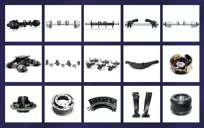
An axle is a rod or shaft that connects to the drive wheels
An axle is a rod or shaft that is fixed to the drive wheels of a vehicle. It provides support and rotates with the wheels. Generally, a vehicle has two axles. However, larger vehicles can have more. The type of axle used will depend on how much torque and speed the wheels need to travel.
Drive axles are crucial to the operation of a car. They transfer power from the engine to the wheels, so they must be strong and durable. They also need to be able to support the weight of the vehicle and resist accelerated forces. The drive axle is usually connected to a driveshaft, which extends upward into the transmission and connects with the engine.
There are two main types of axles: front wheel drive (FWD) and rear wheel drive (RWD). The former type is common in passenger vehicles, while the latter type is more common for trucks and cars. The rear wheel drive (RWD) axle connects to the drive wheels, while the front-wheel drive (FWD) axle transfers power from the transaxle differential to the wheels.
Modern drive axles consist of short rods with a flexible rubber boot covering the CV joint. The rubber boot helps to prevent dirt and grease from getting into the CV joint. The increased complexity of the drive axle increases the risk that something goes wrong with it. However, this increases the car’s traction, ride quality, and handling.
A car’s axles are designed by engineers to be extremely strong. They must be able to withstand thousands of pounds of weight, while operating under high levels of friction. But no drive axle is invincible; they will break if the vehicle is overloaded or too heavy.
The rear axle is connected to the engine and rotates with the wheels. The front axle helps with steering and absorbs road shocks. Typically, this part is made of carbon steel and nickel steel.
It absorbs braking and acceleration forces
The Axle is an important part of a vehicle’s suspension. It is responsible for absorbing braking and acceleration forces. Axle roll centres are located on the transversal vertical plane, through the center of each wheel. This is the point at which lateral force applied to the sprung mass is transferred to the unsprung mass, a process known as transfer of momentum. This force coupling point is also known as the Neutral Roll Axis.
An axle’s role in a vehicle goes beyond absorbing braking and acceleration forces. It also serves as a weight transfer device, reducing the stress on the joints of a vehicle. Its design has evolved over time to meet a variety of requirements. It must be durable and able to absorb braking and acceleration forces, while providing the right amount of structural support.
A potential diagram can be used to benchmark tyre performance. The data entered can include suspension geometry and load distributions. The lateral force potential of a tyre is calculated for each individual tyre in an axle, and the values obtained for a constant steer angle are also included.
Optimal energy recovery is crucial for absorbing braking forces and meeting the total braking force required for a given deceleration. Figure 11 shows the braking forces for the front and rear axles over a certain range when j/g = m. The thick solid line ab represents this range.
In addition to braking and acceleration forces, an axle’s lateral force capacity is limited by lateral load transfer. If one axle fails to absorb lateral forces, it might break loose and skid before the other. This can lead to understeer and oversteer. This is why it is not a good idea to put unsprung weight on a vehicle’s axle.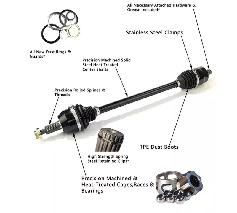
It transmits power from the engine to the wheels
The axle is an integral part of a vehicle’s drive system. It transmits power from the engine to the wheels. Different types of axles have different roles in transmission of power from the engine to the wheels. The drive shaft is the main component of an axle, connecting the engine and the wheels.
A vehicle’s axle transmits power from the engine to the rear wheels. The power is transferred through the gears to move the car forward. The inner wheel of a bicycle pedal powers the back wheel, while the outer wheel moves at a different speed. Similarly, the power from the engine is transmitted to the wheels by a car’s crankshaft and driveshaft.
The type of axle you choose depends on the size of the vehicle and its purpose. Standard axles are suitable for most vehicles, while customized axles are best suited for high-performance vehicles. Customized axles give you more control over the wheel speed and torque. It’s important to know about the types and sizes of axles to choose the right one for your vehicle.
A differential is another vital component of the drivetrain. It allows the power from the engine to reach both wheels, which allows the vehicle to accelerate and decelerate. A differential also compensates for the difference in tyre speeds on curved roads. By using a differential, you can increase the speed of the wheels and improve your car’s handling.
The differential between the front and rear axles is called a bevel ring gear. Its input shaft is supported by a ball race mounted in the axle casing. The other part of the differential is called the input helical gear. The two sun gears are connected by cross-pins.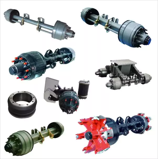
It is a simple machine for amplifying force
A simple machine is one that increases the output of force without altering the input force. For example, a lever increases force but does not create new energy. Therefore, it is necessary to balance the work input and output. It is important to keep in mind that friction can reduce energy.
Using a simple machine, you can perform various tasks. For example, you can use it to cut and pry apart objects. This type of machine involves a wheel and an axle, which have a smaller radius than the wedge. The force applied by the wheel pushes the two pieces apart.
Another simple machine that amplifies force is a gearbox. The earliest gearboxes were used to lift buckets or weights from wells. The large gear is attached to a smaller one by a hinge. The smaller gear increases the force of the larger one, allowing the small gear to lift much larger loads.
A wheel and axle is a simple machine that uses mechanical advantage to change force. A wheel is a circular disk, and an axle is a rod through the center. The mechanical advantage is a result of the combination of torque and angular momentum to work against the force of gravity. In addition, this machine is closely related to gears.
Simple machines are a great way to compare the magnitude of forces, as they use similar mechanisms. One of the oldest examples of a simple machine is a wheel and axle. A wheel is fixed to an axle, and the axle is fixed to a vertical surface. The force generated by the wheel will be proportional to the distance between the two spools.
Another simple machine that amplifies force is a lever. A lever uses a beam or a rigid rod that can pivot on its fulcrum. It is an effective tool for shifting heavy loads, and also for applying force. It also reduces the friction of a vehicle while preserving its momentum.
editor by czh 2022-12-07
China Custom on-Grid Solar Horizontal Single Axis with Linkage Motor Drive Tracker System for Solar Power Plant with high quality
Product Description
Product Description
Single Axis Solar Panel Independent Tracking System with Linkage Motor Drive
Single Axis Panel Independent Tracking System with Linkage Motor Drive uses rotary linkage motor drive, double row connected at the same time drive, higher strength, stronger stability. It can track the sunlight in real time and search for light intelligently. Comparing with thetraditional fixed bracket, the power generation can be increased by 10-15%. This system is suitable for multi scene large power station.
Features
1, The traditional square tube girder design has better adaptability.
2, Adopting fishbone purlin, which is better strength, better stability and easy installation.
3, Max. gradient difference adaptability in N-S direction up to 15%.
4, Excellent compatibility with all the mainstream solar modules available in the industry: frame, frameless and bi-facial. Independent 2V module design, which reduces the quantity of piles and the construction cost significantly.
5, Free obstacles among trackers in N-S direction, easy to maintain and clean.
6, Its design is configured with 1 single set of controller, which ensures point-to-point real-time monitoring, easy to detect fault points in time every day and reduce output loss.
7, Reducing the cost and energy consumption comparing with single axis with independent tracking system.
8, Independent design, various land form adaptability.
| Product Advantages |
| Middle rotary drive, 2 measuring belts damping, enhance damping, reduce resonance. |
| Rotary drive system, tracking angle can be reached ±60° |
| The linkage shaft can be adjusted in all directions, and is not affected by high and low staggering. |
| Single motor drive, greatly reduce the cost. |
| System Advantages |
| String power, backup battery, safe and reliable |
| Wireless communication, optimized layout, simple and efficient |
| Intelligent tracking all day to improve power generation |
| Internet cloud data transmission, 5G transmission, real-time monitoring, fast and efficient. |
Product Parameters
| Electrical system parameters | |
| Control mode | MCU |
| Tracking accuracy | 2° |
| Protection level | IP65 |
| Ambient temperature | -40ºC-85ºC |
| Power supply type | AC110-500/DC 300-1500 |
| Monitoring device | Remote monitoring(optional) |
| Communication mode | Wireless / wired communication |
| System basic parameters | |
| Driving form | Rotary device |
| Foundation type | Cement foundation / Steel pile foundation |
| Component type | Single glass panel / double glass panel / frameless panel |
| Tracking range | ± 50 ° |
| Panel layout | Single row vertical/ double row vertical |
| Minimum height above ground | 0.3m(lowest point) |
| System life | More than 30 years |
| Work speed | ≤18m/s |
| Resistance to wind speed | ≤50m/s |
Detailed Photos
Project
Company Profile
ZHangZhoug ChuHangZhou New Energy Co., Ltd, was established in 1999, headquartered in HangZhou city, half an hour from ZheJiang city by speed train. With 22 years of production experience, the quality has been certified by TUV, SGS, ISO 9001 etc. As a leader in the global photovoltaic system industry, the company focuses on the research and development, design, production, engineering installation services and system solutions of support structure products, with application in photovoltaic and construction.
Chuanda‘s main business includes aluminum frame, PV mounting and tracking system, distributed power station development, pipe corridor brackets etc. It is 1 the largest professional manufacturer of PV mounting and tracking system in China and the Asia-Pacific region. ChuHangZhou is committed to providing professional, efficient, and reliable photovoltaic system solutions to global customers. As of 2571, the cumulative global installation of photovoltaic mounting and tracking system has exceeded 15 GW, the cumulative turnover of all the business exceeds 1 billion in RMB.
Workshop
Certifications
Cooperation Partners
FAQ
Q: Are you a manufacturer or a Trading company?
A: We are a leader manufacturer of solar PV mounting systems and related accessories since 1999, with rich practical experience and mature production technology, and has several production lines, and our products have won the favor of customers from all over the world.
Q: What can you get from us?
A: -Professional analysis on the project, supply professional design and drawings from the engineers team
-Big annual capacity of 5GW will guarantee the fast delivery for all the clients
-24H services before selling and after selling from our engineers team and sales team
-High quality control system to guarantee the high quality for every order
-Competitive price from good management on supplier-chain system and high automated equipment
-New products launching every year
-New information from market and industry updating every month
-5 years’ warranty
Q: How to guarantee the quality?
A: – A counter sample will be confirmed and sealed by both sides before bulk production.
-The professional prodution technical instruction is available for all the bulk procedure.
-3 QC steps for every order, including incoming material inspetion, on-site inspection and final inspection.
– Professional testing will be done according to the detailed standard.
Q: Why we are better?
A: – Big production capacity, 2 production base in China.
– Rich production experience, we have 22 years in this industry.
– More than 30 professional engineers for quality control and R&D.
– Competitive price, 5-10% better than the market price, as we have a good raw material supplier chain and quality control system.
Worm Shafts and Gearboxes
If you have a gearbox, you may be wondering what the best Worm Shaft is for your application. There are several things to consider, including the Concave shape, Number of threads, and Lubrication. This article will explain each factor and help you choose the right Worm Shaft for your gearbox. There are many options available on the market, so don’t hesitate to shop around. If you are new to the world of gearboxes, read on to learn more about this popular type of gearbox.
Concave shape
The geometry of a worm gear varies considerably depending on its manufacturer and its intended use. Early worms had a basic profile that resembled a screw thread and could be chased on a lathe. Later, tools with a straight sided g-angle were developed to produce threads that were parallel to the worm’s axis. Grinding was also developed to improve the finish of worm threads and minimize distortions that occur with hardening.
To select a worm with the proper geometry, the diameter of the worm gear must be in the same unit as the worm’s shaft. Once the basic profile of the worm gear is determined, the worm gear teeth can be specified. The calculation also involves an angle for the worm shaft to prevent it from overheating. The angle of the worm shaft should be as close to the vertical axis as possible.
Double-enveloping worm gears, on the other hand, do not have a throat around the worm. They are helical gears with a straight worm shaft. Since the teeth of the worm are in contact with each other, they produce significant friction. Unlike double-enveloping worm gears, non-throated worm gears are more compact and can handle smaller loads. They are also easy to manufacture.
The worm gears of different manufacturers offer many advantages. For instance, worm gears are 1 of the most efficient ways to increase torque, while lower-quality materials like bronze are difficult to lubricate. Worm gears also have a low failure rate because they allow for considerable leeway in the design process. Despite the differences between the 2 standards, the overall performance of a worm gear system is the same.
The cone-shaped worm is another type. This is a technological scheme that combines a straight worm shaft with a concave arc. The concave arc is also a useful utility model. Worms with this shape have more than 3 contacts at the same time, which means they can reduce a large diameter without excessive wear. It is also a relatively low-cost model.
Thread pattern
A good worm gear requires a perfect thread pattern. There are a few key parameters that determine how good a thread pattern is. Firstly, the threading pattern must be ACME-threaded. If this is not possible, the thread must be made with straight sides. Then, the linear pitch of the “worm” must be the same as the circular pitch of the corresponding worm wheel. In simple terms, this means the pitch of the “worm” is the same as the circular pitch of the worm wheel. A quick-change gearbox is usually used with this type of worm gear. Alternatively, lead-screw change gears are used instead of a quick-change gear box. The pitch of a worm gear equals the helix angle of a screw.
A worm gear’s axial pitch must match the circular pitch of a gear with a higher axial pitch. The circular pitch is the distance between the points of teeth on the worm, while the axial pitch is the distance between the worm’s teeth. Another factor is the worm’s lead angle. The angle between the pitch cylinder and worm shaft is called its lead angle, and the higher the lead angle, the greater the efficiency of a gear.
Worm gear tooth geometry varies depending on the manufacturer and intended use. In early worms, threading resembled the thread on a screw, and was easily chased using a lathe. Later, grinding improved worm thread finishes and minimized distortions from hardening. As a result, today, most worm gears have a thread pattern corresponding to their size. When selecting a worm gear, make sure to check for the number of threads before purchasing it.
A worm gear’s threading is crucial in its operation. Worm teeth are typically cylindrical, and are arranged in a pattern similar to screw or nut threads. Worm teeth are often formed on an axis of perpendicular compared to their parallel counterparts. Because of this, they have greater torque than their spur gear counterparts. Moreover, the gearing has a low output speed and high torque.
Number of threads
Different types of worm gears use different numbers of threads on their planetary gears. A single threaded worm gear should not be used with a double-threaded worm. A single-threaded worm gear should be used with a single-threaded worm. Single-threaded worms are more effective for speed reduction than double-threaded ones.
The number of threads on a worm’s shaft is a ratio that compares the pitch diameter and number of teeth. In general, worms have 1,2,4 threads, but some have three, five, or six. Counting thread starts can help you determine the number of threads on a worm. A single-threaded worm has fewer threads than a multiple-threaded worm, but a multi-threaded worm will have more threads than a mono-threaded planetary gear.
To measure the number of threads on a worm shaft, a small fixture with 2 ground faces is used. The worm must be removed from its housing so that the finished thread area can be inspected. After identifying the number of threads, simple measurements of the worm’s outside diameter and thread depth are taken. Once the worm has been accounted for, a cast of the tooth space is made using epoxy material. The casting is moulded between the 2 tooth flanks. The V-block fixture rests against the outside diameter of the worm.
The circular pitch of a worm and its axial pitch must match the circular pitch of a larger gear. The axial pitch of a worm is the distance between the points of the teeth on a worm’s pitch diameter. The lead of a thread is the distance a thread travels in 1 revolution. The lead angle is the tangent to the helix of a thread on a cylinder.
The worm gear’s speed transmission ratio is based on the number of threads. A worm gear with a high ratio can be easily reduced in 1 step by using a set of worm gears. However, a multi-thread worm will have more than 2 threads. The worm gear is also more efficient than single-threaded gears. And a worm gear with a high ratio will allow the motor to be used in a variety of applications.
Lubrication
The lubrication of a worm gear is particularly challenging, due to its friction and high sliding contact force. Fortunately, there are several options for lubricants, such as compounded oils. Compounded oils are mineral-based lubricants formulated with 10 percent or more fatty acid, rust and oxidation inhibitors, and other additives. This combination results in improved lubricity, reduced friction, and lower sliding wear.
When choosing a lubricant for a worm shaft, make sure the product’s viscosity is right for the type of gearing used. A low viscosity will make the gearbox difficult to actuate and rotate. Worm gears also undergo a greater sliding motion than rolling motion, so grease must be able to migrate evenly throughout the gearbox. Repeated sliding motions will push the grease away from the contact zone.
Another consideration is the backlash of the gears. Worm gears have high gear ratios, sometimes 300:1. This is important for power applications, but is at the same time inefficient. Worm gears can generate heat during the sliding motion, so a high-quality lubricant is essential. This type of lubricant will reduce heat and ensure optimal performance. The following tips will help you choose the right lubricant for your worm gear.
In low-speed applications, a grease lubricant may be sufficient. In higher-speed applications, it’s best to apply a synthetic lubricant to prevent premature failure and tooth wear. In both cases, lubricant choice depends on the tangential and rotational speed. It is important to follow manufacturer’s guidelines regarding the choice of lubricant. But remember that lubricant choice is not an easy task.
China wholesaler China Suppliers Belt Conveyor Drum Head Pulley Drive Drum with Motor and Gear Reducer Box with Free Design Custom
Product Description
China Suppliers Belt Conveyor Drum Head Pulley Drive Drum with Motor and Gear Reducer Box
YILUN conveyor pulley is manufactured as per customer requirement, with main design under national standard, quality inspection focusing on shaft core, welded joint, rubber material and hardness, dynamic balance, and so on for longer product lifetime.
Our products are widely used in thermal power generation, harbors, cement plants, metallurgy and as well as light-duty conveying devices for industries.
Product Parameters
| Application | recycling industry power industry parcel transport industry petro industry coal mining industry cement concrete industry machining industry |
| Pipe/Tube/Shell | 1)Material: Q235 Steel 2)Diameter:219mm-3000mm 3)Length:500mm-5000mm, depending on the belt width of the conveyor |
| Shaft/Axis | Material:#45 Steel |
| Bearing | Big roving crack, deep groove ball with double sealing |
| Welding | Pipe and bearing housing with automatic welding |
| Surface | Smooth steel color surface, rubber lagging surface |
| Color | Red, green, blue, or as required |
| Working life | ≥30000 hours |
| Standard | GB,ISO,DIN,CEMA,JIS |
| Special | can be customized according to the customer or designed for the customer |
| Supply Ability | 50 pcs per day |
| Certificate | ISO9001:2008, BV, SGS |
Quality inspection
Our Advantages
Yilun Conveyor Drum Pulley Advantage:
1. Dust-proof & Water-proof
The contact-sealing is adopted, which enjoys more superior dustproof and waterproof
2. Low Vibration and Noise
Static balance test to ensure G40 accuracy level.
3. Strong Force of Friction
The material for the shaft is forged shaft of 40Cr instead of #45 round steel,which improves mechanical property
4. Easy Installation & Simple Maintenance
The bearing block and taper-lock are ground, which ensures the installation precision
5. Min 50000 hours of service life
Product Features
| Conveyor Pulley Test | 1. All butt welds shall be full Penetration 2. All welds to be full seal welds to prevent rust 3. Shell seam welds are submerged arc (SAW) 4. Includes stress relieving of shell prior to machining 5. Ultrasonic testing of all shafts 6. Drillings for Temperature probe/vibration analysis device 7. Remove all butts and sharp edges |
| Conveyor Pulley Shaft Selection | The major cause of conveyor pulley failure is excessive shaft deflection. The Conveyor Pulleys – ZheJiang HSCD Engineering department can perform Stress Analysis and Finite Element Analysis to maximize your conveyor pulley performance. |
| Conveyor Pulley Shell Material | Q345B Carbon Steel GR350 Carbon Steel ANSI 4140 Alloy Steel ASTM A514B Stainless Steel |
| Bearing House | NSK/ /HRB/LYC, as customer request. |
| Conveyor Pulley Lagging | Plain rubber lagging, Herringbone, and CZPT grooves are all available . Hot Vulcanised Durometer . Hardness 50-55-65 Shore A, M Grade . Oil Resistant, Heat Resistant FRAS |
| Comprising | •Drive pulley, Head pulley, and Tail Pulleys •Take-Up Pulleys, •Snub pulley & Bend Pulleys •Self Cleaning Spiral CZPT pulley & Drum Pulleys |
| Significant advantages | • The thick pulley shell absorbs more stress. • The large crown angle provides superior belt tracking capabilities. • True concentric machining provides: • maximum contact with the belt, • consistent belt content discharge, • less deflection of shaft, • less stress on the bearings |
| Available Conveyor Pulley Designs |
•Liveshaft or Deadshaft types. •Flat or crowned shell. •Taconite, labyrinth, or specialty seals. •Oil or grease lubricated. • Self-centering or low-pressure lock element designs. |
Packaging & Shipping
Iron Pallet Packing of Convey Pulley for shipping in 20ft or 40ft containers.
Customer visiting&Exhibitions
After Sales Service
We give our customers the greatest support in after-sale service.
1. Send the engineer to train how to install the conveyor face to face;
2. Any problems can be solved online in time;
3. Conveyor/Roller/Idler Parts are available in stock.
4. Strict Quality Control to keep the long lifetime.
What kinds of Conveyor Pulleys we can manufacture:
·Conveyor head pulley, Conveyor drive pulley, Conveyor bend pulley, Conveyor Tail Pulley
·Conveyor tension pulley, Conveyor snub Pulley, Conveyor CZPT Pulley, Conveyor take up Pulley, and so on
Company Profile
HangZhou CZPT Conveying Machinery Co., LTD was founded in 2005, It is located in the economic and development zone of Xihu (West Lake) Dis., HangZhou city, Shangdong Province. Our company is specialize in fixed conveyors, movable and going up and down conveyers with type TD75, DTII, and DTIIA. the roller and drum/pulley. Our company also gain some product patent.it also improves our brand “YILUN” and also implores new markets, such as Europe, Australia, South Africa, the Middle East, Africa, etc.
FAQ:
1. Q: Is your bearing type and brand usually used?
A: Large ball bearing type deep ball bearing with SRB, and according to customer’s requirements.
2. Q: How is your Payment Term?
A: T/T or L/C. Another payment term we can also discuss.
3. Q: Can you customize it?
A: We support customization according to your request.
4. Q: What’s the MOQ?
A: 3 pieces.
5. Q: What’s the production capacity of your conveyor pulley?
20 pcs/day.
6. Q: What’s your roller’s lifetime?
Our pulley has a long life with good performance and usually
makes sure 30000 to 50000 hours under the normal site and operation.
If you are interested in us, pls contact me ^ ^
How to Calculate the Diameter of a Worm Gear

In this article, we will discuss the characteristics of the Duplex, Single-throated, and Undercut worm gears and the analysis of worm shaft deflection. Besides that, we will explore how the diameter of a worm gear is calculated. If you have any doubt about the function of a worm gear, you can refer to the table below. Also, keep in mind that a worm gear has several important parameters which determine its working.
Duplex worm gear
A duplex worm gear set is distinguished by its ability to maintain precise angles and high gear ratios. The backlash of the gearing can be readjusted several times. The axial position of the worm shaft can be determined by adjusting screws on the housing cover. This feature allows for low backlash engagement of the worm tooth pitch with the worm gear. This feature is especially beneficial when backlash is a critical factor when selecting gears.
The standard worm gear shaft requires less lubrication than its dual counterpart. Worm gears are difficult to lubricate because they are sliding rather than rotating. They also have fewer moving parts and fewer points of failure. The disadvantage of a worm gear is that you cannot reverse the direction of power due to friction between the worm and the wheel. Because of this, they are best used in machines that operate at low speeds.
Worm wheels have teeth that form a helix. This helix produces axial thrust forces, depending on the hand of the helix and the direction of rotation. To handle these forces, the worms should be mounted securely using dowel pins, step shafts, and dowel pins. To prevent the worm from shifting, the worm wheel axis must be aligned with the center of the worm wheel’s face width.
The backlash of the CZPT duplex worm gear is adjustable. By shifting the worm axially, the section of the worm with the desired tooth thickness is in contact with the wheel. As a result, the backlash is adjustable. Worm gears are an excellent choice for rotary tables, high-precision reversing applications, and ultra-low-backlash gearboxes. Axial shift backlash is a major advantage of duplex worm gears, and this feature translates into a simple and fast assembly process.
When choosing a gear set, the size and lubrication process will be crucial. If you’re not careful, you might end up with a damaged gear or 1 with improper backlash. Luckily, there are some simple ways to maintain the proper tooth contact and backlash of your worm gears, ensuring long-term reliability and performance. As with any gear set, proper lubrication will ensure your worm gears last for years to come.
Single-throated worm gear
Worm gears mesh by sliding and rolling motions, but sliding contact dominates at high reduction ratios. Worm gears’ efficiency is limited by the friction and heat generated during sliding, so lubrication is necessary to maintain optimal efficiency. The worm and gear are usually made of dissimilar metals, such as phosphor-bronze or hardened steel. MC nylon, a synthetic engineering plastic, is often used for the shaft.
Worm gears are highly efficient in transmission of power and are adaptable to various types of machinery and devices. Their low output speed and high torque make them a popular choice for power transmission. A single-throated worm gear is easy to assemble and lock. A double-throated worm gear requires 2 shafts, 1 for each worm gear. Both styles are efficient in high-torque applications.
Worm gears are widely used in power transmission applications because of their low speed and compact design. A numerical model was developed to calculate the quasi-static load sharing between gears and mating surfaces. The influence coefficient method allows fast computing of the deformation of the gear surface and local contact of the mating surfaces. The resultant analysis shows that a single-throated worm gear can reduce the amount of energy required to drive an electric motor.
In addition to the wear caused by friction, a worm wheel can experience additional wear. Because the worm wheel is softer than the worm, most of the wear occurs on the wheel. In fact, the number of teeth on a worm wheel should not match its thread count. A single-throated worm gear shaft can increase the efficiency of a machine by as much as 35%. In addition, it can lower the cost of running.
A worm gear is used when the diametrical pitch of the worm wheel and worm gear are the same. If the diametrical pitch of both gears is the same, the 2 worms will mesh properly. In addition, the worm wheel and worm will be attached to each other with a set screw. This screw is inserted into the hub and then secured with a locknut.
Undercut worm gear
Undercut worm gears have a cylindrical shaft, and their teeth are shaped in an evolution-like pattern. Worms are made of a hardened cemented metal, 16MnCr5. The number of gear teeth is determined by the pressure angle at the zero gearing correction. The teeth are convex in normal and centre-line sections. The diameter of the worm is determined by the worm’s tangential profile, d1. Undercut worm gears are used when the number of teeth in the cylinder is large, and when the shaft is rigid enough to resist excessive load.
The center-line distance of the worm gears is the distance from the worm centre to the outer diameter. This distance affects the worm’s deflection and its safety. Enter a specific value for the bearing distance. Then, the software proposes a range of suitable solutions based on the number of teeth and the module. The table of solutions contains various options, and the selected variant is transferred to the main calculation.
A pressure-angle-angle-compensated worm can be manufactured using single-pointed lathe tools or end mills. The worm’s diameter and depth are influenced by the cutter used. In addition, the diameter of the grinding wheel determines the profile of the worm. If the worm is cut too deep, it will result in undercutting. Despite the undercutting risk, the design of worm gearing is flexible and allows considerable freedom.
The reduction ratio of a worm gear is massive. With only a little effort, the worm gear can significantly reduce speed and torque. In contrast, conventional gear sets need to make multiple reductions to get the same reduction level. Worm gears also have several disadvantages. Worm gears can’t reverse the direction of power because the friction between the worm and the wheel makes this impossible. The worm gear can’t reverse the direction of power, but the worm moves from 1 direction to another.
The process of undercutting is closely related to the profile of the worm. The worm’s profile will vary depending on the worm diameter, lead angle, and grinding wheel diameter. The worm’s profile will change if the generating process has removed material from the tooth base. A small undercut reduces tooth strength and reduces contact. For smaller gears, a minimum of 14-1/2degPA gears should be used.
Analysis of worm shaft deflection
To analyze the worm shaft deflection, we first derived its maximum deflection value. The deflection is calculated using the Euler-Bernoulli method and Timoshenko shear deformation. Then, we calculated the moment of inertia and the area of the transverse section using CAD software. In our analysis, we used the results of the test to compare the resulting parameters with the theoretical ones.
We can use the resulting centre-line distance and worm gear tooth profiles to calculate the required worm deflection. Using these values, we can use the worm gear deflection analysis to ensure the correct bearing size and worm gear teeth. Once we have these values, we can transfer them to the main calculation. Then, we can calculate the worm deflection and its safety. Then, we enter the values into the appropriate tables, and the resulting solutions are automatically transferred into the main calculation. However, we have to keep in mind that the deflection value will not be considered safe if it is larger than the worm gear’s outer diameter.
We use a four-stage process for investigating worm shaft deflection. We first apply the finite element method to compute the deflection and compare the simulation results with the experimentally tested worm shafts. Finally, we perform parameter studies with 15 worm gear toothings without considering the shaft geometry. This step is the first of 4 stages of the investigation. Once we have calculated the deflection, we can use the simulation results to determine the parameters needed to optimize the design.
Using a calculation system to calculate worm shaft deflection, we can determine the efficiency of worm gears. There are several parameters to optimize gearing efficiency, including material and geometry, and lubricant. In addition, we can reduce the bearing losses, which are caused by bearing failures. We can also identify the supporting method for the worm shafts in the options menu. The theoretical section provides further information.
China high quality CZPT Low Speed CE ISO9001 6.5inch 400rpm 100kg Load 24V 48V Gearless Brushless DC Drive Wheel Hub Motor with Encoder for Mobile Robot near me supplier
Product Description
ZLTECH low speed CE ISO9001 6.5inch 400RPM 100kg load 24V 48V gearless brushless DC drive wheel hub motor with encoder for mobile robot
Packaging & Shipping
Package: carton with foam, QTY per carton will depend on the hub motor size.
Shipping: goods will be deliveried by air(EMS, DHL, FedEx,TNT etc), by train or by boat according to your requirements.
Contact:
FAQ
1. Factory or trader?
We are factory, and have professional R&D team as introduced in company information.
2. How about the delivery?
– Sample: 3-5 days.
– Bulk order: 15-30 days.
3. What is your after-sales services?
1. Free maintenance within 12 months guarantee, lifetime consultant.
2. Professional solutions in installation and maintence.
4. Why choose us?
1. Factory Price & 24/7 after-sale services.
2. From mold customization to material processing and welding, from fine components to finished assembly, 72 processes, 24 control points, strict aging, finished product inspection.
What Is a Worm Gear Reducer?
If you have never seen a worm gear reducer before, you’re missing out! Learn more about these incredible gears and their applications by reading this article! In addition to worm gear reducers, learn about worms and how they’re made. You’ll also discover what types of machines can benefit from worm gears, such as rock crushers and elevators. The following information will help you understand what a worm gear reducer is and how to find 1 in your area.
Typical worm shaft
A typical worm has 2 shafts, 1 for advancing and 1 for receding, which form the axial pitch of the gear. Usually, there are 8 standard axial pitches, which establish a basic dimension for worm production and inspection. The axial pitch of the worm equals the circular pitch of the gear in the central plane and the master lead cam’s radial pitch. A single set of change gears and 1 master lead cam are used to produce each size of worm.
Worm gear is commonly used to manufacture a worm shaft. It is a reliable and efficient gear reduction system that does not move when the power is removed. Typical worm gears come in standard sizes as well as assisted systems. Manufacturers can be found online. Listed below are some common materials for worm gears. There are also many options for lubrication. The worm gear is typically made from case hardened steel or bronze. Non-metallic materials are also used in light-duty applications.
A self-locking worm gear prevents the worm from moving backwards. Typical worm gears are generally self-locking when the lead angle is less than 11 degrees. However, this feature can be detrimental to systems that require reverse sensitivity. If the lead angle is less than 4 degrees, back-driving is unlikely. However, if fail-safe protection is a prerequisite, back-driving worm gears must have a positive brake to avoid reverse movement.
Worm gears are often used in transmission applications. They are a more efficient way to reduce the speed of a machine compared to conventional gear sets. Their reduced speed is possible thanks to their low ratio and few components. Unlike conventional gear sets, worm gears require less maintenance and lower mechanical failure than a conventional gear set. While they require fewer parts, worm gears are also more durable than conventional gear sets.
There are 2 types of worm tooth forms. Convex and involute helicoids have different types of teeth. The former uses a straight line to intersect the involute worm generating line. The latter, on the other hand, uses a trapezoid based on the central cross section of the root. Both of these tooth forms are used in the production of worms. And they have various variations in pitch diameter.
Types of worms
Worms have several forms of tooth. For convenience in production, a trapezoid-based tooth form is used. Other forms include an involute helicoidal or a convolute worm generating a line. The following is a description of each type. All types are similar, and some may be preferred over others. Listed below are the 3 most common worm shaft types. Each type has its own advantages and disadvantages.
Discrete versus parallel axis: The design of a worm gear determines its ratio of torque. It’s a combination of 2 different metals – 1 for the worm and 1 for the wheel – which helps it absorb shock loads. Construction equipment and off-road vehicles typically require varying torques to maneuver over different terrain. A worm gear system can help them maneuver over uneven terrain without causing excessive wear.
Worm gear units have the highest ratio. The sliding action of the worm shaft results in a high self-locking torque. Depending on the angle of inclination and friction, a worm gear can reach up to 100:1! Worm gears can be made of different materials depending on their inclination and friction angle. Worm gears are also useful for gear reduction applications, such as lubrication or grinding. However, you should consider that heavier gears tend to be harder to reverse than lighter ones.
Metal alloy: Stainless steel, brass, and aluminum bronze are common materials for worm gears. All 3 types have unique advantages. A bronze worm gear is typically composed of a combination of copper, zinc, and tin. A bronze shaft is more corrosive than a brass one, but it is a durable and corrosion-resistant option. Metal alloys: These materials are used for both the worm wheel.
The efficiency of worm gears depends on the assembly conditions and the lubricant. A 30:1 ratio reduces the efficiency to 81:1%. A worm gear is more efficient at higher ratios than an helical gear, but a 30:1 ratio reduces the efficiency to 81%. A helical gear reduces speed while preserving torque to around 15% of the original speed. The difference in efficiency between worm gear and helical gear is about half an hour!
Methods of manufacturing worm shafts
Several methods of manufacturing worm shafts are available in the market. Single-pointed lathe tools or end mills are the most popular methods for manufacturing worms. These tools are capable of producing worms with different pressure angles depending on their diameter, the depth of thread, and the grinding wheel’s diameter. The diagram below shows how different pressure angles influence the profile of worms manufactured using different cutting tools.
The method for making worm shafts involves the process of establishing the proper outer diameter of a common worm shaft blank. This may include considering the number of reduction ratios in a family, the distance between the worm shaft and the gear set center, as well as the torques involved. These processes are also referred to as ‘thread assembly’. Each process can be further refined if the desired axial pitch can be achieved.
The axial pitch of a worm must match the circular pitch of the larger gear. This is called the pitch. The pitch diameter and axial pitch must be equal. Worms can be left-handed or right-handed. The lead, which refers to the distance a point on the thread travels during 1 revolution of the worm, is defined by its angle of tangent to the helix on the pitch of the cylinder.
Worm shafts are commonly manufactured using a worm gear. Worm gears can be used in different applications because they offer fine adjustment and high gear reduction. They can be made in both standard sizes and assisted systems. Worm shaft manufacturers can be found online. Alternatively, you can contact a manufacturer directly to get your worm gears manufactured. The process will take only a few minutes. If you are looking for a manufacturer of worm gears, you can browse a directory.
Worm gears are made with hardened metal. The worm wheel and gear are yellow in color. A compounded oil with rust and oxidation inhibitors is also used to make worm gears. These oils adhere to the shaft walls and make a protective barrier between the surfaces. If the compounded oil is applied correctly, the worm gear will reduce the noise in a motor, resulting in a smoother performance.
applications for worm gear reducers
Worm gears are widely used in power transmission applications, providing a compact, high reduction, low-speed drive. To determine the torque ratio of worm gears, a numerical model was developed that makes use of the equation of displacement compatibility and the influence coefficient method, which provides fast computing. The numerical model also incorporates bending deflections of the gear surfaces and the mating surfaces. It is based on the Boussinesq theory, which calculates local contact deformations.
Worm gears can be designed to be right or left-handed, and the worm can turn either clockwise or counter-clockwise. An internal helical gear requires the same hand to operate both parts. In contrast, an external helical gear must be operated by the opposite hand. The same principle applies to worm gears in other applications. The torque and power transferred can be large, but worm gears are able to cope with large reductions in both directions.
Worm gears are extremely useful in industrial machinery designs. They reduce noise levels, save space, and give machines extra precision and fast-stopping capabilities. Worm gears are also available in compact versions, making them ideal for hoisting applications. This type of gear reducer is used in industrial settings where space is an issue. Its smaller size and less noise makes it ideal for applications that need the machine to stop quickly.
A double-throated worm gear offers the highest load capacity while still remaining compact. The double-throated version features concave teeth on both worm and gear, doubling the contact area between them. Worm gears are also useful for low to moderate-horsepower applications, and their high ratios, high output torque, and significant speed reduction make them a desirable choice for many applications. Worm gears are also quieter than other types of gears, reducing the noise and vibrations that they cause.
Worm gears have numerous advantages over other types of gears. They have high levels of conformity and can be classified as a screw pair within a lower-pair gear family. Worm gears are also known to have a high degree of relative sliding. Worm gears are often made of hardened steel or phosphor-bronze, which provides good surface finish and rigid positioning. Worm gears are lubricated with special lubricants that contain surface-active additives. Worm gear lubrication is a mixed lubrication process and causes mild wear and tear.
China Best Sales CZPT M400 MID Drive Motor E-Bike 48V/10.4ah Integrated Battery Electric Bicycle near me supplier
Product Description
Specification
| Electric system | |
| Motor | Light weight high speed brushless |
| 250W/350w CZPT M400 high speed brushless central motor | |
| Battery | 36V10Ah or 48V 10AH native/Samsung Li-ion battery |
| PAS | Torque Sensor |
| Controller | intelligent bruhsless. |
| Charger | AC 100V -240V 2amps smart charger |
| Charging time:4-6hours | |
| Performance | |
| Max speed | 25km/h (EU) |
| Range | 60-70km with 36V/10Ah li-ion battery(torque sensor). |
| Max load | 120kgs |
| Net weight | 27kgs |
| Gross weight | 30kgs |
| Container load | 90pcs/20ft container,180pcs/40ft container |
| Display | Smart CZPT LCD display |
| Main components | |
| Frame | 6061 aluminium alloy. |
| Tyres | 700C CST/Kender tyre |
| Rim | Al alloy double wall and CNC side wall. |
| Front fork | TGS/SUNTOUR Al alloy fork with suspension function |
| Front brake | TEKTRO Disc brake |
| Rear brake | TEKTRO Disc brake |
| Speed gears | SHIMANO Acera 8 speeds |
| Rear derailleur | SHIMANO Acera 8 speeds |
| Stem | al alloy . |
| Brake lever | Al alloy with power off switch. PROMAX/TEKTRO |
| Chain | KMC Rust resistant chain. |
| Chain wheel | al alloy crank. |
| Mudguard | YES |
| Saddle | Comfortable SR Saddle from Italy |
| Lighting | front & rear light. LED |
| Pedal | Foldablestyle pedal . |
| Packing size | 147 x 27 x 74cm special for exporting |
More detailed pictures
Delivery and Package
Company Information
LOHAS VEHICLE is an electric bicycle factory which is located in HangZhou city, ZHangZhoug Province which is near ZheJiang and HangZhou . High speed train straight to arrive to our company.
We have more than 10years OEM experience, supported by top Technical Team and excellent Sales Team.
After developing the new electric bicycle,Staff in our company keep riding the bikes for commuter everyday ,to test the stability ,also to improve the model from every aspect.
FAQ
1. What’s the minimum order MOQ?
Our MOQ is 15pcs(30 pcs is required for special model )
2. What is the production and delivery time?
Production time is from 15 to 50days. Depending on the models.
3. Can I order a sample?
Yes. we will send a sample to you by shipping or DHL/TNT, but you must pay the sample and shipping or DHL/TNT fee.
4. How about warranty ?
alloy frame 3 years , motor 1 years, lithium battery 2 years, controller 1 years.
5. Could I use my own LOGO or design on goods?
Yes. When order quantity is big, you can use your own LOGO or your language manual etc,
6. Does company accept EURO ?
Yes. We also have EURO account, not only USD.
7. What is the payment terms?
We accept T/T, L/C, DP, DA , OA, West Union
8. How can I go to the factory ?
our factory is located in HangZhou city, ZHangZhoug province, China.
It is 1.5 hours by air from HangZhou; 2 hours by D-train from Shangha to HangZhou ;
9. Can we mix the 20ft/40ft/40HQ container?
Yes, you can mix it , you can mix 2-5 models in a 20FCL container for Alloy Electric bicycle
Contact us:
Thank you very much for visiting our website on alibaba. And also welcome to visit our factory.
LOHAS VEHICLE
Analytical Approaches to Estimating Contact Pressures in Spline Couplings
A spline coupling is a type of mechanical connection between 2 rotating shafts. It consists of 2 parts – a coupler and a coupling. Both parts have teeth which engage and transfer loads. However, spline couplings are typically over-dimensioned, which makes them susceptible to fatigue and static behavior. Wear phenomena can also cause the coupling to fail. For this reason, proper spline coupling design is essential for achieving optimum performance.
Modeling a spline coupling
Spline couplings are becoming increasingly popular in the aerospace industry, but they operate in a slightly misaligned state, causing both vibrations and damage to the contact surfaces. To solve this problem, this article offers analytical approaches for estimating the contact pressures in a spline coupling. Specifically, this article compares analytical approaches with pure numerical approaches to demonstrate the benefits of an analytical approach.
To model a spline coupling, first you create the knowledge base for the spline coupling. The knowledge base includes a large number of possible specification values, which are related to each other. If you modify 1 specification, it may lead to a warning for violating another. To make the design valid, you must create a spline coupling model that meets the specified specification values.
After you have modeled the geometry, you must enter the contact pressures of the 2 spline couplings. Then, you need to determine the position of the pitch circle of the spline. In Figure 2, the centre of the male coupling is superposed to that of the female spline. Then, you need to make sure that the alignment meshing distance of the 2 splines is the same.
Once you have the data you need to create a spline coupling model, you can begin by entering the specifications for the interface design. Once you have this data, you need to choose whether to optimize the internal spline or the external spline. You’ll also need to specify the tooth friction coefficient, which is used to determine the stresses in the spline coupling model 20. You should also enter the pilot clearance, which is the clearance between the tip 186 of a tooth 32 on 1 spline and the feature on the mating spline.
After you have entered the desired specifications for the external spline, you can enter the parameters for the internal spline. For example, you can enter the outer diameter limit 154 of the major snap 54 and the minor snap 56 of the internal spline. The values of these parameters are displayed in color-coded boxes on the Spline Inputs and Configuration GUI screen 80. Once the parameters are entered, you’ll be presented with a geometric representation of the spline coupling model 20.
Creating a spline coupling model 20
The spline coupling model 20 is created by a product model software program 10. The software validates the spline coupling model against a knowledge base of configuration-dependent specification constraints and relationships. This report is then input to the ANSYS stress analyzer program. It lists the spline coupling model 20’s geometric configurations and specification values for each feature. The spline coupling model 20 is automatically recreated every time the configuration or performance specifications of the spline coupling model 20 are modified.
The spline coupling model 20 can be configured using the product model software program 10. A user specifies the axial length of the spline stack, which may be zero, or a fixed length. The user also enters a radial mating face 148, if any, and selects a pilot clearance specification value of 14.5 degrees or 30 degrees.
A user can then use the mouse 110 to modify the spline coupling model 20. The spline coupling knowledge base contains a large number of possible specification values and the spline coupling design rule. If the user tries to change a spline coupling model, the model will show a warning about a violation of another specification. In some cases, the modification may invalidate the design.
In the spline coupling model 20, the user enters additional performance requirement specifications. The user chooses the locations where maximum torque is transferred for the internal and external splines 38 and 40. The maximum torque transfer location is determined by the attachment configuration of the hardware to the shafts. Once this is selected, the user can click “Next” to save the model. A preview of the spline coupling model 20 is displayed.
The model 20 is a representation of a spline coupling. The spline specifications are entered in the order and arrangement as specified on the spline coupling model 20 GUI screen. Once the spline coupling specifications are entered, the product model software program 10 will incorporate them into the spline coupling model 20. This is the last step in spline coupling model creation.
Analysing a spline coupling model 20
An analysis of a spline coupling model consists of inputting its configuration and performance specifications. These specifications may be generated from another computer program. The product model software program 10 then uses its internal knowledge base of configuration dependent specification relationships and constraints to create a valid three-dimensional parametric model 20. This model contains information describing the number and types of spline teeth 32, snaps 34, and shoulder 36.
When you are analysing a spline coupling, the software program 10 will include default values for various specifications. The spline coupling model 20 comprises an internal spline 38 and an external spline 40. Each of the splines includes its own set of parameters, such as its depth, width, length, and radii. The external spline 40 will also contain its own set of parameters, such as its orientation.
Upon selecting these parameters, the software program will perform various analyses on the spline coupling model 20. The software program 10 calculates the nominal and maximal tooth bearing stresses and fatigue life of a spline coupling. It will also determine the difference in torsional windup between an internal and an external spline. The output file from the analysis will be a report file containing model configuration and specification data. The output file may also be used by other computer programs for further analysis.
Once these parameters are set, the user enters the design criteria for the spline coupling model 20. In this step, the user specifies the locations of maximum torque transfer for both the external and internal spline 38. The maximum torque transfer location depends on the configuration of the hardware attached to the shafts. The user may enter up to 4 different performance requirement specifications for each spline.
The results of the analysis show that there are 2 phases of spline coupling. The first phase shows a large increase in stress and vibration. The second phase shows a decline in both stress and vibration levels. The third stage shows a constant meshing force between 300N and 320N. This behavior continues for a longer period of time, until the final stage engages with the surface.
Misalignment of a spline coupling
A study aimed to investigate the position of the resultant contact force in a spline coupling engaging teeth under a steady torque and rotating misalignment. The study used numerical methods based on Finite Element Method (FEM) models. It produced numerical results for nominal conditions and parallel offset misalignment. The study considered 2 levels of misalignment – 0.02 mm and 0.08 mm – with different loading levels.
The results showed that the misalignment between the splines and rotors causes a change in the meshing force of the spline-rotor coupling system. Its dynamics is governed by the meshing force of splines. The meshing force of a misaligned spline coupling is related to the rotor-spline coupling system parameters, the transmitting torque, and the dynamic vibration displacement.
Despite the lack of precise measurements, the misalignment of splines is a common problem. This problem is compounded by the fact that splines usually feature backlash. This backlash is the result of the misaligned spline. The authors analyzed several splines, varying pitch diameters, and length/diameter ratios.
A spline coupling is a two-dimensional mechanical system, which has positive backlash. The spline coupling is comprised of a hub and shaft, and has tip-to-root clearances that are larger than the backlash. A form-clearance is sufficient to prevent tip-to-root fillet contact. The torque on the splines is transmitted via friction.
When a spline coupling is misaligned, a torque-biased thrust force is generated. In such a situation, the force can exceed the torque, causing the component to lose its alignment. The two-way transmission of torque and thrust is modeled analytically in the present study. The analytical approach provides solutions that can be integrated into the design process. So, the next time you are faced with a misaligned spline coupling problem, make sure to use an analytical approach!
In this study, the spline coupling is analyzed under nominal conditions without a parallel offset misalignment. The stiffness values obtained are the percentage difference between the nominal pitch diameter and load application diameter. Moreover, the maximum percentage difference in the measured pitch diameter is 1.60% under a torque of 5000 N*m. The other parameter, the pitch angle, is taken into consideration in the calculation.
China Standard CZPT CE ISO9001 8inch 24V 48V 600rpm 100kg Load Gearless Brushless Electric Drive Wheel DC Hub Servo Motor with Encoder for Mobile Robot near me supplier
Product Description
Zltech CE ISO9001 8Inch 24V 48V 600rpm 100kg Load gearless Brushless Electric Drive Wheel DC Hub Servo Motor with Encoder for mobile robot
Packaging & Shipping
Package: carton with foam, QTY per carton will depend on the hub motor size.
Shipping: goods will be deliveried by air(EMS, DHL, FedEx,TNT etc), by train or by boat according to your requirements.
Contact:
FAQ
1. Factory or trader?
We are factory, and have professional R&D team as introduced in company information.
2. How about the delivery?
– Sample: 3-5 days.
– Bulk order: 15-30 days.
3. What is your after-sales services?
1. Free maintenance within 12 months guarantee, lifetime consultant.
2. Professional solutions in installation and maintence.
4. Why choose us?
1. Factory Price & 24/7 after-sale services.
2. From mold customization to material processing and welding, from fine components to finished assembly, 72 processes, 24 control points, strict aging, finished product inspection.
Worm Shafts and Gearboxes
If you have a gearbox, you may be wondering what the best Worm Shaft is for your application. There are several things to consider, including the Concave shape, Number of threads, and Lubrication. This article will explain each factor and help you choose the right Worm Shaft for your gearbox. There are many options available on the market, so don’t hesitate to shop around. If you are new to the world of gearboxes, read on to learn more about this popular type of gearbox.
Concave shape
The geometry of a worm gear varies considerably depending on its manufacturer and its intended use. Early worms had a basic profile that resembled a screw thread and could be chased on a lathe. Later, tools with a straight sided g-angle were developed to produce threads that were parallel to the worm’s axis. Grinding was also developed to improve the finish of worm threads and minimize distortions that occur with hardening.
To select a worm with the proper geometry, the diameter of the worm gear must be in the same unit as the worm’s shaft. Once the basic profile of the worm gear is determined, the worm gear teeth can be specified. The calculation also involves an angle for the worm shaft to prevent it from overheating. The angle of the worm shaft should be as close to the vertical axis as possible.
Double-enveloping worm gears, on the other hand, do not have a throat around the worm. They are helical gears with a straight worm shaft. Since the teeth of the worm are in contact with each other, they produce significant friction. Unlike double-enveloping worm gears, non-throated worm gears are more compact and can handle smaller loads. They are also easy to manufacture.
The worm gears of different manufacturers offer many advantages. For instance, worm gears are 1 of the most efficient ways to increase torque, while lower-quality materials like bronze are difficult to lubricate. Worm gears also have a low failure rate because they allow for considerable leeway in the design process. Despite the differences between the 2 standards, the overall performance of a worm gear system is the same.
The cone-shaped worm is another type. This is a technological scheme that combines a straight worm shaft with a concave arc. The concave arc is also a useful utility model. Worms with this shape have more than 3 contacts at the same time, which means they can reduce a large diameter without excessive wear. It is also a relatively low-cost model.
Thread pattern
A good worm gear requires a perfect thread pattern. There are a few key parameters that determine how good a thread pattern is. Firstly, the threading pattern must be ACME-threaded. If this is not possible, the thread must be made with straight sides. Then, the linear pitch of the “worm” must be the same as the circular pitch of the corresponding worm wheel. In simple terms, this means the pitch of the “worm” is the same as the circular pitch of the worm wheel. A quick-change gearbox is usually used with this type of worm gear. Alternatively, lead-screw change gears are used instead of a quick-change gear box. The pitch of a worm gear equals the helix angle of a screw.
A worm gear’s axial pitch must match the circular pitch of a gear with a higher axial pitch. The circular pitch is the distance between the points of teeth on the worm, while the axial pitch is the distance between the worm’s teeth. Another factor is the worm’s lead angle. The angle between the pitch cylinder and worm shaft is called its lead angle, and the higher the lead angle, the greater the efficiency of a gear.
Worm gear tooth geometry varies depending on the manufacturer and intended use. In early worms, threading resembled the thread on a screw, and was easily chased using a lathe. Later, grinding improved worm thread finishes and minimized distortions from hardening. As a result, today, most worm gears have a thread pattern corresponding to their size. When selecting a worm gear, make sure to check for the number of threads before purchasing it.
A worm gear’s threading is crucial in its operation. Worm teeth are typically cylindrical, and are arranged in a pattern similar to screw or nut threads. Worm teeth are often formed on an axis of perpendicular compared to their parallel counterparts. Because of this, they have greater torque than their spur gear counterparts. Moreover, the gearing has a low output speed and high torque.
Number of threads
Different types of worm gears use different numbers of threads on their planetary gears. A single threaded worm gear should not be used with a double-threaded worm. A single-threaded worm gear should be used with a single-threaded worm. Single-threaded worms are more effective for speed reduction than double-threaded ones.
The number of threads on a worm’s shaft is a ratio that compares the pitch diameter and number of teeth. In general, worms have 1,2,4 threads, but some have three, five, or six. Counting thread starts can help you determine the number of threads on a worm. A single-threaded worm has fewer threads than a multiple-threaded worm, but a multi-threaded worm will have more threads than a mono-threaded planetary gear.
To measure the number of threads on a worm shaft, a small fixture with 2 ground faces is used. The worm must be removed from its housing so that the finished thread area can be inspected. After identifying the number of threads, simple measurements of the worm’s outside diameter and thread depth are taken. Once the worm has been accounted for, a cast of the tooth space is made using epoxy material. The casting is moulded between the 2 tooth flanks. The V-block fixture rests against the outside diameter of the worm.
The circular pitch of a worm and its axial pitch must match the circular pitch of a larger gear. The axial pitch of a worm is the distance between the points of the teeth on a worm’s pitch diameter. The lead of a thread is the distance a thread travels in 1 revolution. The lead angle is the tangent to the helix of a thread on a cylinder.
The worm gear’s speed transmission ratio is based on the number of threads. A worm gear with a high ratio can be easily reduced in 1 step by using a set of worm gears. However, a multi-thread worm will have more than 2 threads. The worm gear is also more efficient than single-threaded gears. And a worm gear with a high ratio will allow the motor to be used in a variety of applications.
Lubrication
The lubrication of a worm gear is particularly challenging, due to its friction and high sliding contact force. Fortunately, there are several options for lubricants, such as compounded oils. Compounded oils are mineral-based lubricants formulated with 10 percent or more fatty acid, rust and oxidation inhibitors, and other additives. This combination results in improved lubricity, reduced friction, and lower sliding wear.
When choosing a lubricant for a worm shaft, make sure the product’s viscosity is right for the type of gearing used. A low viscosity will make the gearbox difficult to actuate and rotate. Worm gears also undergo a greater sliding motion than rolling motion, so grease must be able to migrate evenly throughout the gearbox. Repeated sliding motions will push the grease away from the contact zone.
Another consideration is the backlash of the gears. Worm gears have high gear ratios, sometimes 300:1. This is important for power applications, but is at the same time inefficient. Worm gears can generate heat during the sliding motion, so a high-quality lubricant is essential. This type of lubricant will reduce heat and ensure optimal performance. The following tips will help you choose the right lubricant for your worm gear.
In low-speed applications, a grease lubricant may be sufficient. In higher-speed applications, it’s best to apply a synthetic lubricant to prevent premature failure and tooth wear. In both cases, lubricant choice depends on the tangential and rotational speed. It is important to follow manufacturer’s guidelines regarding the choice of lubricant. But remember that lubricant choice is not an easy task.
China Professional High Reliable Mobile Motor Drive /Electric Driven Type Screw Rechargeable Portable Air near me manufacturer
Product Description
The machine can meet the demands of overloading use and stands up to the most severe filed environment. Meanwhile, it also can reduce fuel consumption,which greatly cut down the operation cost. Subsided structure to install the oil tank, placed around each one, Increase oil reserves, make the add oil time interval longer, the weight on both sides are balanced. Tank not in the case, make the space more and not only bring convenience to maintenance service, noise is reduced accordingly, but also giving the customer a good value feeling.
Advantage:
1. High Reliability
Less compressor parts, without wearing parts, so it is reliable, long life, overhaul interval is up to 40 to 80 thousand hours.
2. Easy Operation and Maintenance
A high degree of automation, the operator does not have to go through a long period of professional training, can achieve unattended operation.
3. The Power Balance is Good
There is no unbalanced inertia force, can smoothly high-speed operation, can achieve no basic operation, especially suitable for portable compressors, small size, light weight, small footprint.
4. Strong Adaptability
With a mandatory gas transmission characteristics, the volume flow is almost free from the impact of exhaust pressure, in a wide range of speed to maintain high efficiency.
COMPS COMPRESSOR (HangZhou) Co., Ltd is located in HangZhou of China. The company covers about 185177632
Stiffness and Torsional Vibration of Spline-Couplings
In this paper, we describe some basic characteristics of spline-coupling and examine its torsional vibration behavior. We also explore the effect of spline misalignment on rotor-spline coupling. These results will assist in the design of improved spline-coupling systems for various applications. The results are presented in Table 1.
Stiffness of spline-coupling
The stiffness of a spline-coupling is a function of the meshing force between the splines in a rotor-spline coupling system and the static vibration displacement. The meshing force depends on the coupling parameters such as the transmitting torque and the spline thickness. It increases nonlinearly with the spline thickness.
A simplified spline-coupling model can be used to evaluate the load distribution of splines under vibration and transient loads. The axle spline sleeve is displaced a z-direction and a resistance moment T is applied to the outer face of the sleeve. This simple model can satisfy a wide range of engineering requirements but may suffer from complex loading conditions. Its asymmetric clearance may affect its engagement behavior and stress distribution patterns.
The results of the simulations show that the maximum vibration acceleration in both Figures 10 and 22 was 3.03 g/s. This results indicate that a misalignment in the circumferential direction increases the instantaneous impact. Asymmetry in the coupling geometry is also found in the meshing. The right-side spline’s teeth mesh tightly while those on the left side are misaligned.
Considering the spline-coupling geometry, a semi-analytical model is used to compute stiffness. This model is a simplified form of a classical spline-coupling model, with submatrices defining the shape and stiffness of the joint. As the design clearance is a known value, the stiffness of a spline-coupling system can be analyzed using the same formula.
The results of the simulations also show that the spline-coupling system can be modeled using MASTA, a high-level commercial CAE tool for transmission analysis. In this case, the spline segments were modeled as a series of spline segments with variable stiffness, which was calculated based on the initial gap between spline teeth. Then, the spline segments were modelled as a series of splines of increasing stiffness, accounting for different manufacturing variations. The resulting analysis of the spline-coupling geometry is compared to those of the finite-element approach.
Despite the high stiffness of a spline-coupling system, the contact status of the contact surfaces often changes. In addition, spline coupling affects the lateral vibration and deformation of the rotor. However, stiffness nonlinearity is not well studied in splined rotors because of the lack of a fully analytical model.
Characteristics of spline-coupling
The study of spline-coupling involves a number of design factors. These include weight, materials, and performance requirements. Weight is particularly important in the aeronautics field. Weight is often an issue for design engineers because materials have varying dimensional stability, weight, and durability. Additionally, space constraints and other configuration restrictions may require the use of spline-couplings in certain applications.
The main parameters to consider for any spline-coupling design are the maximum principal stress, the maldistribution factor, and the maximum tooth-bearing stress. The magnitude of each of these parameters must be smaller than or equal to the external spline diameter, in order to provide stability. The outer diameter of the spline must be at least 4 inches larger than the inner diameter of the spline.
Once the physical design is validated, the spline coupling knowledge base is created. This model is pre-programmed and stores the design parameter signals, including performance and manufacturing constraints. It then compares the parameter values to the design rule signals, and constructs a geometric representation of the spline coupling. A visual model is created from the input signals, and can be manipulated by changing different parameters and specifications.
The stiffness of a spline joint is another important parameter for determining the spline-coupling stiffness. The stiffness distribution of the spline joint affects the rotor’s lateral vibration and deformation. A finite element method is a useful technique for obtaining lateral stiffness of spline joints. This method involves many mesh refinements and requires a high computational cost.
The diameter of the spline-coupling must be large enough to transmit the torque. A spline with a larger diameter may have greater torque-transmitting capacity because it has a smaller circumference. However, the larger diameter of a spline is thinner than the shaft, and the latter may be more suitable if the torque is spread over a greater number of teeth.
Spline-couplings are classified according to their tooth profile along the axial and radial directions. The radial and axial tooth profiles affect the component’s behavior and wear damage. Splines with a crowned tooth profile are prone to angular misalignment. Typically, these spline-couplings are oversized to ensure durability and safety.
Stiffness of spline-coupling in torsional vibration analysis
This article presents a general framework for the study of torsional vibration caused by the stiffness of spline-couplings in aero-engines. It is based on a previous study on spline-couplings. It is characterized by the following 3 factors: bending stiffness, total flexibility, and tangential stiffness. The first criterion is the equivalent diameter of external and internal splines. Both the spline-coupling stiffness and the displacement of splines are evaluated by using the derivative of the total flexibility.
The stiffness of a spline joint can vary based on the distribution of load along the spline. Variables affecting the stiffness of spline joints include the torque level, tooth indexing errors, and misalignment. To explore the effects of these variables, an analytical formula is developed. The method is applicable for various kinds of spline joints, such as splines with multiple components.
Despite the difficulty of calculating spline-coupling stiffness, it is possible to model the contact between the teeth of the shaft and the hub using an analytical approach. This approach helps in determining key magnitudes of coupling operation such as contact peak pressures, reaction moments, and angular momentum. This approach allows for accurate results for spline-couplings and is suitable for both torsional vibration and structural vibration analysis.
The stiffness of spline-coupling is commonly assumed to be rigid in dynamic models. However, various dynamic phenomena associated with spline joints must be captured in high-fidelity drivetrain models. To accomplish this, a general analytical stiffness formulation is proposed based on a semi-analytical spline load distribution model. The resulting stiffness matrix contains radial and tilting stiffness values as well as torsional stiffness. The analysis is further simplified with the blockwise inversion method.
It is essential to consider the torsional vibration of a power transmission system before selecting the coupling. An accurate analysis of torsional vibration is crucial for coupling safety. This article also discusses case studies of spline shaft wear and torsionally-induced failures. The discussion will conclude with the development of a robust and efficient method to simulate these problems in real-life scenarios.
Effect of spline misalignment on rotor-spline coupling
In this study, the effect of spline misalignment in rotor-spline coupling is investigated. The stability boundary and mechanism of rotor instability are analyzed. We find that the meshing force of a misaligned spline coupling increases nonlinearly with spline thickness. The results demonstrate that the misalignment is responsible for the instability of the rotor-spline coupling system.
An intentional spline misalignment is introduced to achieve an interference fit and zero backlash condition. This leads to uneven load distribution among the spline teeth. A further spline misalignment of 50um can result in rotor-spline coupling failure. The maximum tensile root stress shifted to the left under this condition.
Positive spline misalignment increases the gear mesh misalignment. Conversely, negative spline misalignment has no effect. The right-handed spline misalignment is opposite to the helix hand. The high contact area is moved from the center to the left side. In both cases, gear mesh is misaligned due to deflection and tilting of the gear under load.
This variation of the tooth surface is measured as the change in clearance in the transverse plain. The radial and axial clearance values are the same, while the difference between the 2 is less. In addition to the frictional force, the axial clearance of the splines is the same, which increases the gear mesh misalignment. Hence, the same procedure can be used to determine the frictional force of a rotor-spline coupling.
Gear mesh misalignment influences spline-rotor coupling performance. This misalignment changes the distribution of the gear mesh and alters contact and bending stresses. Therefore, it is essential to understand the effects of misalignment in spline couplings. Using a simplified system of helical gear pair, Hong et al. examined the load distribution along the tooth interface of the spline. This misalignment caused the flank contact pattern to change. The misaligned teeth exhibited deflection under load and developed a tilting moment on the gear.
The effect of spline misalignment in rotor-spline couplings is minimized by using a mechanism that reduces backlash. The mechanism comprises cooperably splined male and female members. One member is formed by 2 coaxially aligned splined segments with end surfaces shaped to engage in sliding relationship. The connecting device applies axial loads to these segments, causing them to rotate relative to 1 another.
China Hot selling New Suspension Fork CZPT BBS HD MID Drive Motor 1000W 27.5 Inch Electric Bike with Great quality
Product Description
Product Description
Features
1.500W motor with water proof connector
2.Disc brake for both
3.48V 13AH Lithium Battery(Sumsung cells)
4.LCD display
5.LED light for front and battery light for rear
6.Hydraulic suspension fork with lock
7.7 speed CZPT gear shift
|
Frame |
Aluminum alloy frame |
||
|
Motor |
500W G060 CZPT motor |
||
|
Battery |
48V 13AH Lithium battery |
||
|
Display |
LCD display |
||
|
Light |
LED light for front |
||
|
Tire |
26”×4.0 Kenda Tire |
||
|
Brake |
Disc brake for both |
||
|
Front Fork |
Aluminum alloy |
||
|
Derailleurs |
7 speed CZPT gear shift |
||
|
Max speed |
25km/h-32km/h |
||
|
Driving distance |
Approx 45-70km |
||
|
Loading capacity |
120KGS |
||
|
Packing size |
160×28×80cm |
||
|
Container loads |
80pcs/20’GP; 200pcs/40’HQ |
||
Certifications
Company Profile
Packaging & Shipping
FAQ
1. Warranty policy
a.) For main electronic parts, charger, controller and battery, we provide 6 months warranty.
b.) For motor, we provide 12 months warranty.
c.) For frame, handlebar, stem and wheel rim we provide 2 years warranty.
1.1 The following conditions, not including in warranty policy
a.) Any damages caused by human factor.
b.) Dismounting any parts without professional technical people.
c.) Use other parts in our electric bike or scooter.
d.) Damages caused by traffic accident and other accident.
e.) The problem caused by overloading.
2. Technical support
a.) We provide “electric circuit diagram” for each model.
b.) We can train customer’s 1 or 2 technical workers for free.
c.) When oversea customers meet serious problem, they can not work out by technican, we will dispatch engineer to customer’s company to give help.
FAQ
1. Can I order sample?
Answer: Yes, we accept sample for trial order?
2. How long for delivery time?
Answer: For sample order, our delivery time is 20 to 30days; for 1 full container, it’s 25 to 45days.
3. Which colores will be available?
Answer: Normally, we will introduce the most popular colores to customers. At the same time, we are CZPT to make colores according to customer’s demands.
4. Can I use my logo(sticker) on the electric bike?
Answer: Yes, we can make customer’s logo(sticker) on the electric bike for 1 full container order.
5. How to delivery to foreign buyer?
Answer: For sample order, the customer can select by sea or by air. For full container order, by sea is the best choice.
6. Need I assemble parts of the electric bike when we get them?
Answer: Yes, we will take out few parts, like pedals(if have), mirrors(if have), front wheel, front fender, and rear trunk(if have) before package. Our workers will put these parts in electric bike cartons. And will send 1 professional tool bag to help you assemble. It’s easy to make it.
7. Can I mix different models in 1 full container order?
Answer: Yes, we accept different models in 1 full container.
8. Need I buy spare parts for first order?
Answer: Yes, you need to buy some spare parts for future service. The quantity depends on your electric bike order. We will give you advice when you need.
Our service
1. OEM Manufacturing welcome: Product, Package…
2. Sample order
3. We will reply you for your inquiry in 24 hours.
4. After sending, we will track the products for you once every 2 days, until you get the products. When you got the goods, test them, and give me a feedback.If you have any questions about the problem, contact with us, we will offer the solve way for you.
How to Identify a Faulty Drive Shaft
The most common problems associated with automotive driveshafts include clicking and rubbing noises. While driving, the noise from the driver’s seat is often noticeable. An experienced auto mechanic can easily identify whether the sound is coming from both sides or from 1 side. If you notice any of these signs, it’s time to send your car in for a proper diagnosis. Here’s a guide to determining if your car’s driveshaft is faulty:
Symptoms of Driveshaft Failure
If you’re having trouble turning your car, it’s time to check your vehicle’s driveshaft. A bad driveshaft can limit the overall control of your car, and you should fix it as soon as possible to avoid further problems. Other symptoms of a propshaft failure include strange noises from under the vehicle and difficulty shifting gears. Squeaking from under the vehicle is another sign of a faulty driveshaft.
If your driveshaft fails, your car will stop. Although the engine will still run, the wheels will not turn. You may hear strange noises from under the vehicle, but this is a rare symptom of a propshaft failure. However, you will have plenty of time to fix the problem. If you don’t hear any noise, the problem is not affecting your vehicle’s ability to move.
The most obvious signs of a driveshaft failure are dull sounds, squeaks or vibrations. If the drive shaft is unbalanced, it is likely to damage the transmission. It will require a trailer to remove it from your vehicle. Apart from that, it can also affect your car’s performance and require repairs. So if you hear these signs in your car, be sure to have it checked by a mechanic right away.
Drive shaft assembly
When designing a propshaft, the design should be based on the torque required to drive the vehicle. When this torque is too high, it can cause irreversible failure of the drive shaft. Therefore, a good drive shaft design should have a long service life. Here are some tips to help you design a good driveshaft. Some of the main components of the driveshaft are listed below.
Snap Ring: The snap ring is a removable part that secures the bearing cup assembly in the yoke cross hole. It also has a groove for locating the snap ring. Spline: A spline is a patented tubular machined element with a series of ridges that fit into the grooves of the mating piece. The bearing cup assembly consists of a shaft and end fittings.
U-joint: U-joint is required due to the angular displacement between the T-shaped housing and the pinion. This angle is especially large in raised 4x4s. The design of the U-joint must guarantee a constant rotational speed. Proper driveshaft design must account for the difference in angular velocity between the shafts. The T-bracket and output shaft are attached to the bearing caps at both ends.
U-joint
Your vehicle has a set of U-joints on the driveshaft. If your vehicle needs to be replaced, you can do it yourself. You will need a hammer, ratchet and socket. In order to remove the U-joint, you must first remove the bearing cup. In some cases you will need to use a hammer to remove the bearing cup, you should be careful as you don’t want to damage the drive shaft. If you cannot remove the bearing cup, you can also use a vise to press it out.
There are 2 types of U-joints. One is held by a yoke and the other is held by a c-clamp. A full ring is safer and ideal for vehicles that are often used off-road. In some cases, a full circle can be used to repair a c-clamp u-joint.
In addition to excessive torque, extreme loads and improper lubrication are common causes of U-joint failure. The U-joint on the driveshaft can also be damaged if the engine is modified. If you are driving a vehicle with a heavily modified engine, it is not enough to replace the OE U-joint. In this case, it is important to take the time to properly lubricate these components as needed to keep them functional.
tube yoke
QU40866 Tube Yoke is a common replacement for damaged or damaged driveshaft tubes. They are desirably made of a metallic material, such as an aluminum alloy, and include a hollow portion with a lug structure at 1 end. Tube yokes can be manufactured using a variety of methods, including casting and forging. A common method involves drawing solid elements and machining them into the final shape. The resulting components are less expensive to produce, especially when compared to other forms.
The tube fork has a connection point to the driveshaft tube. The lug structure provides attachment points for the gimbal. Typically, the driveshaft tube is 5 inches in diameter and the lug structure is 4 inches in diameter. The lug structure also serves as a mounting point for the drive shaft. Once installed, Tube Yoke is easy to maintain. There are 2 types of lug structures: 1 is forged tube yoke and the other is welded.
Heavy-duty series drive shafts use bearing plates to secure the yoke to the U-joint. All other dimensions are secured with external snap rings. Yokes are usually machined to accept U-bolts. For some applications, grease fittings are used. This attachment is more suitable for off-road vehicles and performance vehicles.
end yoke
The end yoke of the drive shaft is an integral part of the drive train. Choosing a high-quality end yoke will help ensure long-term operation and prevent premature failure. Pat’s Driveline offers a complete line of automotive end yokes for power take-offs, differentials and auxiliary equipment. They can also measure your existing parts and provide you with high quality replacements.
A U-bolt is an industrial fastener with threaded legs. When used on a driveshaft, it provides greater stability in unstable terrain. You can purchase a U-bolt kit to secure the pinion carrier to the drive shaft. U-bolts also come with lock washers and nuts. Performance cars and off-road vehicles often use this type of attachment. But before you install it, you have to make sure the yoke is machined to accept it.
End yokes can be made of aluminum or steel and are designed to provide strength. It also offers special bolt styles for various applications. CZPT’s drivetrain is also stocked with a full line of automotive flange yokes. The company also produces custom flanged yokes for many popular brands. Since the company has a comprehensive line of replacement flange yokes, it can help you transform your drivetrain from non-serviceable to serviceable.
bushing
The first step in repairing or replacing an automotive driveshaft is to replace worn or damaged bushings. These bushings are located inside the drive shaft to provide a smooth, safe ride. The shaft rotates in a rubber sleeve. If a bushing needs to be replaced, you should first check the manual for recommendations. Some of these components may also need to be replaced, such as the clutch or swingarm.
China best 1000W 48V MID Drive Motor Electric Bike Big Power Snow Electric Bicycle Fat Tyre Mountain Ebike with Full Suspension for Adults Wholesale Factory in China with Best Sales
Product Description
2571 Lohas HI-END fat tire electric bike with 1000w mid drive motor
Specification
| Electric system | Main components | ||
| Motor | 1000w CZPT mid drive motor G510 | Frame | 6061 aluminium alloy. |
| Tyres | 26″ ×4.0 Kenda | ||
| Battery | 48V 17.5AH battery | Rim | Al alloy double wall and CNC side wall. |
| Front fork | RST Xihu (West Lake) Dis. with Suspenion and Lockout | ||
| Front brake | Tektro Hydraulic Disc Brake | ||
| PAS | TORQUE SENSOR | Rear brake | Tektro Hydraulic Disc Brake |
| Controller | intelligent bruhsless.12 month warranty | Speed gears | SHIMANO Acera 8 speeds gear |
| Charger | AC 100V -240V 2amps smart charger | Rear derailleur | SHIMANO |
| Charging time:4-6hours 12 month warranty | Stem | al alloy | |
| Performance | Brake lever | With power off switch.Tektro | |
| Max speed | 45km/h (USA & Canada). | Chain | KMC Rust resistant chain. |
| Range | 40-60km per charge | Chain wheel | al alloy crank. |
| Saddle | mountain style saddle. SR | ||
| Max load | 120kgs | Rear suspension | A5 rear shock absorber |
| Net weight | 29.50kgs | Lighting | front LED |
| Gross weight | 32.0kgs | Pedal | Mountain style pedal . |
| Container load | 96pcs/20ft container | Packing size | 165*27*77cm |
More details
Acera 8 speed gear
Rear Shock Absorber
1000w CZPT mid drive G510
Bafang DCP 18 display
8 speed gear shifter
RST XIHU (WEST LAKE) DIS. suspension fork
Company Information
LOHAS VEHICLE is an electric bicycle factory which is located in HangZhou city, ZHangZhoug Province which is near ZheJiang and HangZhou . High speed train straight to arrive to our company.
We have more than 10years OEM experience, supported by top Technical Team and excellent Sales Team.
After developing the new electric bicycle,Staff in our company keep riding the bikes for commuter everyday ,to test the stability ,also to improve the model from every aspect.
FAQ
1. What’s the minimum order MOQ?
Our MOQ is 15pcs(30 pcs is required for special model )
2. What is the production and delivery time?
Production time is from 15 to 50days. Depending on the models.
3. Can I order a sample?
Yes. we will send a sample to you by shipping or DHL/TNT, but you must pay the sample and shipping or DHL/TNT fee.
4. How about warranty ?
alloy frame 3 years , motor 1 years, lithium battery 2 years, controller 1 years.
5. Could I use my own LOGO or design on goods?
Yes. When order quantity is big, you can use your own LOGO or your language manual etc,
6. Does company accept EURO ?
Yes. We also have EURO account, not only USD.
7. What is the payment terms?
We accept T/T, L/C, DP, DA , OA, West Union
8. How can I go to the factory ?
our factory is located in HangZhou city, ZHangZhoug province, China.
It is 1.5 hours by air from HangZhou; 2 hours by D-train from Shangha to HangZhou ;
9. Can we mix the 20ft/40ft/40HQ container?
Yes, you can mix it , you can mix 2-5 models in a 20FCL container for Alloy Electric bicycle
Different parts of the drive shaft
The driveshaft is the flexible rod that transmits torque between the transmission and the differential. The term drive shaft may also refer to a cardan shaft, a transmission shaft or a propeller shaft. Parts of the drive shaft are varied and include:
The driveshaft is a flexible rod that transmits torque from the transmission to the differential
When the driveshaft in your car starts to fail, you should seek professional help as soon as possible to fix the problem. A damaged driveshaft can often be heard. This noise sounds like “tak tak” and is usually more pronounced during sharp turns. However, if you can’t hear the noise while driving, you can check the condition of the car yourself.
The drive shaft is an important part of the automobile transmission system. It transfers torque from the transmission to the differential, which then transfers it to the wheels. The system is complex, but still critical to the proper functioning of the car. It is the flexible rod that connects all other parts of the drivetrain. The driveshaft is the most important part of the drivetrain, and understanding its function will make it easier for you to properly maintain your car.
Driveshafts are used in different vehicles, including front-wheel drive, four-wheel drive, and front-engine rear-wheel drive. Drive shafts are also used in motorcycles, locomotives and ships. Common front-engine, rear-wheel drive vehicle configurations are shown below. The type of tube used depends on the size, speed and strength of the drive shaft.
The output shaft is also supported by the output link, which has 2 identical supports. The upper part of the drive module supports a large tapered roller bearing, while the opposite flange end is supported by a parallel roller bearing. This ensures that the torque transfer between the differentials is efficient. If you want to learn more about car differentials, read this article.
It is also known as cardan shaft, propeller shaft or drive shaft
A propshaft or propshaft is a mechanical component that transmits rotation or torque from an engine or transmission to the front or rear wheels of a vehicle. Because the axes are not directly connected to each other, it must allow relative motion. Because of its role in propelling the vehicle, it is important to understand the components of the driveshaft. Here are some common types.
Isokinetic Joint: This type of joint guarantees that the output speed is the same as the input speed. To achieve this, it must be mounted back-to-back on a plane that bisects the drive angle. Then mount the 2 gimbal joints back-to-back and adjust their relative positions so that the velocity changes at 1 joint are offset by the other joint.
Driveshaft: The driveshaft is the transverse shaft that transmits power to the front wheels. Driveshaft: The driveshaft connects the rear differential to the transmission. The shaft is part of a drive shaft assembly that includes a drive shaft, a slip joint, and a universal joint. This shaft provides rotational torque to the drive shaft.
Dual Cardan Joints: This type of driveshaft uses 2 cardan joints mounted back-to-back. The center yoke replaces the intermediate shaft. For the duplex universal joint to work properly, the angle between the input shaft and the output shaft must be equal. Once aligned, the 2 axes will operate as CV joints. An improved version of the dual gimbal is the Thompson coupling, which offers slightly more efficiency at the cost of added complexity.
It transmits torque at different angles between driveline components
A vehicle’s driveline consists of various components that transmit power from the engine to the wheels. This includes axles, propshafts, CV joints and differentials. Together, these components transmit torque at different angles between driveline components. A car’s powertrain can only function properly if all its components work in harmony. Without these components, power from the engine would stop at the transmission, which is not the case with a car.
The CV driveshaft design provides smoother operation at higher operating angles and extends differential and transfer case life. The assembly’s central pivot point intersects the joint angle and transmits smooth rotational power and surface speed through the drivetrain. In some cases, the C.V. “U” connector. Drive shafts are not the best choice because the joint angles of the “U” joints are often substantially unequal and can cause torsional vibration.
Driveshafts also have different names, including driveshafts. A car’s driveshaft transfers torque from the transmission to the differential, which is then distributed to other driveline components. A power take-off (PTO) shaft is similar to a prop shaft. They transmit mechanical power to connected components. They are critical to the performance of any car. If any of these components are damaged, the entire drivetrain will not function properly.
A car’s powertrain can be complex and difficult to maintain. Adding vibration to the drivetrain can cause premature wear and shorten overall life. This driveshaft tip focuses on driveshaft assembly, operation, and maintenance, and how to troubleshoot any problems that may arise. Adding proper solutions to pain points can extend the life of the driveshaft. If you’re in the market for a new or used car, be sure to read this article.
it consists of several parts
“It consists of several parts” is 1 of 7 small prints. This word consists of 10 letters and is 1 of the hardest words to say. However, it can be explained simply by comparing it to a cow’s kidney. The cocoa bean has several parts, and the inside of the cocoa bean before bursting has distinct lines. This article will discuss the different parts of the cocoa bean and provide a fun way to learn more about the word.
Replacement is expensive
Replacing a car’s driveshaft can be an expensive affair, and it’s not the only part that needs servicing. A damaged drive shaft can also cause other problems. This is why getting estimates from different repair shops is essential. Often, a simple repair is cheaper than replacing the entire unit. Listed below are some tips for saving money when replacing a driveshaft. Listed below are some of the costs associated with repairs:
First, learn how to determine if your vehicle needs a driveshaft replacement. Damaged driveshaft components can cause intermittent or lack of power. Additionally, improperly installed or assembled driveshaft components can cause problems with the daily operation of the car. Whenever you suspect that your car needs a driveshaft repair, seek professional advice. A professional mechanic will have the knowledge and experience needed to properly solve the problem.
Second, know which parts need servicing. Check the u-joint bushing. They should be free of crumbs and not cracked. Also, check the center support bearing. If this part is damaged, the entire drive shaft needs to be replaced. Finally, know which parts to replace. The maintenance cost of the drive shaft is significantly lower than the maintenance cost. Finally, determine if the repaired driveshaft is suitable for your vehicle.
If you suspect your driveshaft needs service, make an appointment with a repair shop as soon as possible. If you are experiencing vibration and rough riding, driveshaft repairs may be the best way to prevent costly repairs in the future. Also, if your car is experiencing unusual noise and vibration, a driveshaft repair may be a quick and easy solution. If you don’t know how to diagnose a problem with your car, you can take it to a mechanic for an appointment and a quote.